TM5-6115-593-34
NAVFAC P-8-631-34
TO-35C2-3-463-2
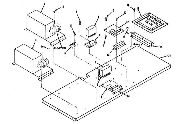
LEGEND
1.
Screw
9.
Socket
16.
Screw
2.
Potentiometer
10.
Screw
17.
Nut
3.
Screw
11.
Nut
18.
AC-DC control
4.
Potentiometer
12.
Time delay module TD3
relay assy
5.
Screw
13.
Screw
19.
Screw
6.
Shunt
14.
Bracket
20.
Bracket
7.
Relay
15.
Integrated time delay
21.
Shelf
8.
Screw
module TD1
Figure 4-10. Component Base Assembly, Exploded View
remove relay assembly (18) and
brackets (20).
(c)
Components are replaced by
carefully unsoldering them from
the printed circuit board.
CAUTION
Do not apply excessive heat when
soldering or unsoldering components.
It may damage the printed circuit
wiring.
(d)
If
AC-DC
Control
Relay
Assembly is to be replaced,
remove screws (16) and nuts
(17) to release relay assembly
(18) from brackets (20).
(e)
Prepare relay assembly (18) for
installation
by
attaching
brackets (20) using screws (16)
and nuts (17).
(f)
If components are being
4-20