TM 5-6115-593-34
NAVFAC P-8-631-34
TO-35C2-3-463-2
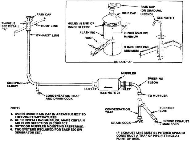
Figure 17-21. 500 KW Exhaust System
The utility monitor circuit which includes 120 VAC
over/under voltage relay (27/59N), under frequency
relay (81N-U), over frequency relay 81N-0), 1.5 - 15
second (adjustable) time delay relay (TD), 50/60Hz
frequency select switch and a run rely (RR), continually
monitors the 120 VAC utility voltage from the line side
of the utility breaker.
When the utility power is normal, relays 27/59N, 81N-U
and TD are energized (81N-0 will only energize during
an over-frequency condition) and the normal power
available lamp will be on.
If the utility power completely fails or voltage varies by
more than ±10% and/or frequency varies more than
±3%, TD relay after a 1.5 - 15 second time delay will
allow all generators to begin a start-up cycle providing
the generators are in the automatic mode. Relays
27/59N, 81N-U, TD and RR de-energize allowing 24
volts D. C. to energize the K5 engine start circuit via
normally closed contacts TD and RR through TB4-5, 6,
7, 8 through J3-B through the automatic position of the
auto-trip manual switch (s53) on each set. The utility
breaker (located within user switchgear will open via
additional sets RR contacts at TB3-17, 18, and 19.
As the generators run up to speed, each generator's
quality circuit (81G-0, 81G-U, 27/59G and CR) monitors
the condition of their respective set. This circuit has
identical voltage and frequency specifications as the
utility monitor circuit in the ACM and is only completely
functional if the generator set is in the automatic mode.
17-28