TM 5-6115-593-34
NAVFAC P-8-631-34
TO-35C2-3-463-2
17-74. The engine exhaust manifold should be
connected to the exhaust piping with a flexible exhaust
connector (see figure 17-20). The flexible exhaust
connector provides a means of taking up thermal growth
of the exhaust system due to the hot exhaust gas and
absorbing vibration.
17-75. Adequate support must be given to the exhaust
piping, no more than 4 feet (12 m) should be allowed to
extend from the engine exhaust manifold without
adequate support.
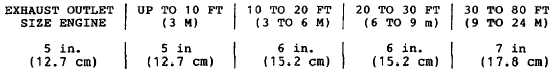
Table 17-8. Exhaust Line Recommendations
NOTE
When installing mufflers, make certain air flow
direction is correct.
17-76. Exhaust piping passing through combustible
walls or partitions shall be guarded at the point of
passage by a metal ventilated thimble not less than 12
inches (30.5 cm) larger in diameter than the exhaust
pipe or metal or burned fire clay thimbles built in
brickwork providing not less than 8 inches (20.3 cm) of
insulation between the thimble and combustible material
(see figure 17-20). Exhaust pipes must not terminate
near inlet vents of any type or near combustible
materials.
17-77. Engine exhaust piping can accumulate a
considerable amount of condensed moisture after unit
shut down, particularly if the exhaust system is run
through lengthy piping. To prevent condensed moisture
from running back into the engine, a condensate trap
and drain should be incorporated at some low point
ahead of the engine manifolds (see figures 17-21
through 17-23).
17-78. Where vertical exhaust stack is necessary, a
rain cap should be fitted to exclude rain and snow from
the exhaust pipe. Fully automatic counter-balanced rain
caps are provided with each generator set.
Section IX. ELECTRICAL REQUIREMENTS
17-79. BATTERIES. The sets lead acid batteries are
shipped dry. They can be stored indefinitely and when
ready to use filled with electrolyte (acid) with a specific
gravity of 1.265 to 1.280. It is recommended that
batteries be placed on charge after electrolyte is added.
17-80. Coat battery terminal connections with grease to
prevent
corrosion.
Check
the
electrolyte
level
periodically. Make certain all battery vent caps are in
place and unobstructed.
17-81. The integral charger will maintain batteries in a
fully charged condition. It will float at a very low rate to
overcome the self-discharge characteristics of idle
batteries.
17-82. SYSTEM DESCRIPTION. The 500 KW DOD
generator set is designed to be used as a single unit or
in conjunction with as many as three additional units.
Two to four units may be paralleled with the use of one
automatic control module (ACM). Another added
feature of the generator set is the ability to either add a
remote set control box or to remove the set's control box
for remote operation. The ACM is designed to
automatically control up to four MEP-029A, 500KW
generator sets.
17-26