TM 5-6115-593-34
NAVFAC P-8-631-34
TO-35C2-3-463-2
17-50. The surge tank should also be equipped with a
sight gauge, overflow pipe, and vent to atomosphere. It
should also have connections for makeup feed water.
17-51. Another important function of the surge tank is
the maintenance of a positive head of pressure on the
engine water pump inlet. The line connecting the
bottom of the surge tank to the engine water pump inlet
services this function.
17-52. The electric auxiliary water pump shown in
figure 17-14 is used to assist the engine driven pump in
maintaining the desired coolant flow rate which would
have been reduced in remoting the radiator by the line
and fitting drop incurred by the additional piping. In the
event of a failure of the auxiliary pump, a bypass valve
connected across the pump can be opened preventing
the complete loss of an emergency standby unit. No
component failure which by itself could prevent
operation should be overlooked.
17-53. A drain valve should be incorporated to facilitate
servicing the radiator. As shown in figure 17-14, the use
of a drain valve and water pump bypass valve permits
the draining of the radiator, surge tank, and the engine.
A strainer is used in the line returning from the radiator
to catch dirt, scale, and core sand.
17-54. The fan motor and electric auxiliary pump must
be connected to ensure their operation whenever the
unit is running.
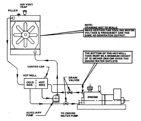
17-55. For applications in which the radiator is
positioned
at
some
distance
above
the
engine
centerline, a hot-well tank and an auxiliary water pump
are
Figure 17-15. Remote Radiator Application "C"
17-18


