TM 5-6115-593-34
NAVFAC P-8-631-34
TO-35C2-3-463-2
top part of the top tank, from 1 to 3 inches (2.54 to 7.62
cm), so that a cushion of air is trapped here to take care
of normal surge.
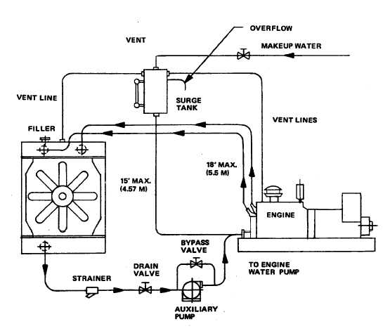
17-45. A strainer is used in the water line returning from
the radiator to catch dirt, scale, and core sand. The
electric auxiliary water pump shown in figure 17-13 is
used to assist the engine driven pump in maintaining the
desired coolant flow rate which would have been
reduced in remoting the radiator by the line and fitting
drop incurred by the additional piping. A drain valve
should be incorporated to facilitate servicing the
radiator.
17-46. The pipe size utilized should be the same size
as the radiator inlet an outlet fittings. Use the same pipe
size throughout the entire system. Use straight lengths
of pipe wherever possible in conjunction with radius
elbows wherever turns are required.
17-47. Flexible hoses used to isolate vibration should
be used at the inlet and outlets of both the engine and
radiator.
17-48. The fan motor and electric auxiliary pump must
be electrically connected to ensure their operation
whenever the unit is running.
17-49. For applications in which the radiator is
positioned at some horizontal distance from the unit and
is not the highest point in the water system the
configuration shown in figure 17-14 is recommended.
The surge tank, located in a position elevated above the
radiator provides the space to accommodate the natural
expansion of heated water and the air and gases
trapped and dissolved in the water. The surge tank is
vented permitting escape of vapor and air.
Figure 17-14. Remote Radiator Application "B"
17-17