TM 5-6115-593-34
NAVFAC P-8-631-34
TO-35C2-3-463-2
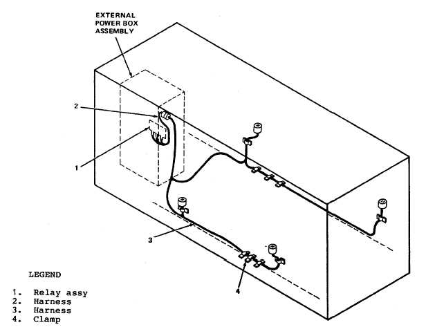
Figure 15-23. Housing Kit Wiring
15-26. REMOVAL. Remove housing kit in the following sequence: Electrical harness, top, rear, left side, front (radiator
end), and right side.
a. Electrical Harness. See figures 15-23 and fold outs FO-14 and FO-15.
WARNING
TURN OFF ALL POWER
(1)
Disconnect jacks and connectors from louver actuators and switches.
(2)
Remove all clamps (4) securing harness (3) to housing kit structure.
(3)
Disconnect J32 from external power box assembly. Remove harness.
(4)
Disconnect harness (2) (in external power box assembly) from TB303 on relay assembly (1) and TB202
and TB203 in the rear wall of external power box assembly.
(5)
Remove relay assembly (1) from rear wall of external power box assembly. Restore existing hardware.
(6)
Remove connector J32 on harness (2) from wall of external power box assembly enclosure.
(7)
Cover hole (created by removing connector J32) with plate.
(8)
Remove harness (2).
15-36