TM 5-6115-593-12
TO 35C2-3-463-1
Table 2-6. Automatic Control Module, Controls and Instruments - Continued
FIGURE,
NORMAL
INDEX NO.
CONTROL AND INSTRUMENT
FUNCTION
READING/SETTING
2-19,12
UNDERFREQUENCY RELAY
Senses utility frequency
— —
(81U)
and trips at 58.2 or
48.5 Hz.
2-19,13
OVERFREQUENCY RELAY
Senses utility frequency
— —
(810)
and trips at 61.8 or
51.5 Hz.
2-19,14
BREAKER CONTROL RELAY
Upon generator circuit
— —
(BR1-BR4)
breaker closure will
provide steering
logic for load relay
circuitry. Auxiliary
contacts provided for
future customer use
of generator circuit
breaker closure in-
dication.
2-19,15
TIME DELAY RELAY (TD)
Delays start of genera-
As desired.
tor(s) upon loss of
utility power.
(Adjustable 1.5-15 sec.)
2-19,16
RUN RELAY (RR)
When de-energized, con-
— —
tacts initiate start
of generator(s).
2-19,17
DIODE PACKS (R1-R4)
Diodes act as logic
— —
steering or blocking
for internal circuitry.
2-19,18
TIME DELAY RELAY (UTR)
Disallows load to be
As desired
transferred back to
utility source until
timed out, if TD
RETURN mode is select-
ed.
(Adjustable 3-30
minutes)
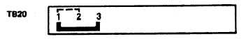
TERMINAL BOARD 20, AC-DC CONTROL BOX
REMOVE JUMPER BETWEEN TERMINALS 1 AND 2 OF TERMINAL
BOARD 20, AND INSTALL JUMPER BETWEEN TERMINALS 1 AND 3.
Figure 2-20. Jumper Connections When Automatic Control Module is Used
2-42