T M 5 - 6 1 1 5 - 5 8 5 - 1 2
N A V F A C P - 8 - 6 2 3 - 12
TO - 35C2 - 3 - 455 - 1
T M - 0 5 6 8 4 C / 0 5 6 8 5 B - 12
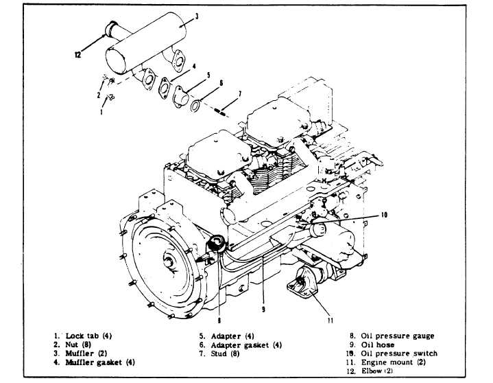
3 - 1 5 . E X H A U ST MUFFLER ASSEMBLY.
Figure 3-6. Exhaust Muffler Assembly
Do not touch muffler assembly while unit is
r u n n i n g o r i m m e d i a t e l y a f t e r s h u t d o w n , as
s e v e r e b u r n s m a y r e s u l t .
a . I n s p e c t ( s e e f i g u r e 3 - 6 ) . M a n u a l l y o p e n s h u t t er
a s s e m b l y a n d c h e c k t h a t m u f f l e r a s s e m b l y ( 3 ) is
securely fastened to unit. Check that nuts (2) and lock
tabs (1) attaching muffler to unit are in place.
Check to see that exhaust is not obstructed and there
is no evidence of leaks.
NOTE
Mount 45° elbows (12) on the mufflers (3) to deflect
exhaust heat away from the batteries.
3 - 1 6.
ENGINE STARTER ASSEMBLY.
a. Cleaning and Inspection (see figure 3-7). On ASK
equipped generators, remove BATTERIES access door.
Clean engine starter (1) by removing loose dirt with a
stiff nonmetallic brush. Clean off remaining dirt and oil
with dry cleaning solvent (Fed. Spec. P-D-680). Inspect
starter to see that electrical connections (4) are clean
and tight. Check to see that mounting bolts (2) are tight.
Check starter (1) for physical damage.
C h a n g e 8 3 - 1 3