TM5-6115-585-12
NAVFAC P-8-262-12
TO-35C2-3-455-1
TM-05684C-12
(11) Relay (K2-K3). Disconnect battery. Tag and
disconnect four leads to relay. Remove two screws
and nuts attaching relay to control cubicle.
(12) Terminal Board Assemblies (TB4 and TB5).
Tag and disconnect leads to terminal boards. Remove
two screws and nuts attaching board to control cubicle
and remove board.
NOTE
TB4 has 27 leads and TB5 has 36 leads.
e. Assembly.
(1) Panel Light Assemblies (DS1 and DS2). Attach
new light assembly to control panel with the nut and
lockwasher supplied with each assembly. Attach two
tagged leads to each panel light (if necessary refer
to wiring diagram, figure 1-7).
(2) Hour Meter (M2). Attach hour meter to control
panel with three screws, lockwashers, and nuts pro-
vided with meter. Attach two tagged leads to meter
(if necessary, refer to wiring diagram, figure 1-7).
(3) Battery Charging Indicator (M1). Slide battery
charging indicator into opening in control panel. Place
retainer over back of indicator and secure with two
lockwashers and nuts. Attach lead to indicator (if
necessary, refer to wiring diagram, figure 1-7).
(4) DC Control Circuit Breaker (CB2). Attach
circuit breaker to control panel with the two screws.
Reconnect tagged leads to breaker (if necessary, refer
to wiring diagram, figure 1-7).
(5) Master Switch (S1). Attach master switch to
control panel with nut and key ring provided with
switch. Make certain key on key ring aligns with slot
in control panel.
Push switch knob onto shaft and
attach with two allen screws. Attach seven tagged
leads to switch (if necessary, refer to wiring dia-
gram, figure 1-7).
(6) Panel Light Switch (S2). Attach panel light
switch to control panel with nut and key ring. Make
certain key on key ring aligns with slot in control
panel. Attach two tagged leads to switch (if necessary,
refer to wiring diagram, figure 1-7).
(7) Voltmeter-Ammeter Range Selector Switch
(S8). Attach range selector switch to control panel
with nut and key ring. Make certain key on key ring
aligns with slot in control panel. Push switch knob
onto shaft and attach with two allen screws. Attach
sixteen tagged leads to switch (if necessary, refer to
wiring diagram, figure 1-7).
(8) Relay (K1). Plug new relay into socket on
relay assembly A1 and secure with two screws.
(9) Relay (K2 and K3). Attach relay to control
cubicle with two screws and nuts. Reconnect four
tagged leads per wiring diagram, figure 1-7.
4-44
(10) Terminal Board Assemblies (TB4) and (TB5).
Attach board to control cubicle with two screws and
nuts. Attach tagged leads to board (if necessary, refer
to schematic, figure 1-10).
(11) Voltage Adjust Rheostat (R1). Attach rheostat
(9) to control panel with nut and lockwasher pro-
vided with rheostat. Make certain that rheostat aligns
with slot on panel. Push rheostat knob onto shaft and
attach using two allen screws. Attach two tagged
leads to rheostat per wiring diagram, figure 1-7.
(12) Transformer (T1). Attach transformer to
control cubicle with four screws and nuts. Connect
five tagged leads to (T1) per wiring diagram, figure
1-7.
(13) Transformer (T2). Attach transformer to
control cubicle with four screws and nuts. Connect
four tagged leads to (T2) per wiring diagram, figure
1-7.
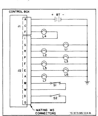
f. Bench Test. Connect the control cubicle as shown
in figure 4-35 and proceed as follows.
(1) Position switches as follows:
(a) Master switch-stop
(b) Panel light switch-off
(c) S1-closed
(d) S2-open
Figure 4-35. Control Cubicle Test Set-Up