TM5-6115-584-34
NAVFAC P-8-622-34
TO-35C2-456-2
(4) Remove the through studs (9), remove
screws (10) and rear cover (11).
(5) Raise the brush springs (12) lift the
brushes (13) and remove brush holder (14).
(6) Remove stator (frame assembly) (15), rear
bearing (16), armature (17) and armature front
bearing (18).
(7) Remove screws (19), cover (20),retaining
ring (21), flat washer (22) and spacer (23).
(8) Remove screw (24) freeing the center
bracket (25).
NOTE
There is a spring force behind screw (24).
(9) Remove and count the flat washers (26),
remove packing (27), outer spring (28), inner
spring (29).
NOTE
Note the direction in which the lever is
installed before removal.
(10) Remove lever (30) and gear (31).
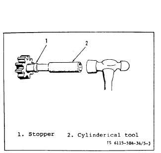
(11) Push stopper (33) towards front bracket
to release retaining ring (32). See figure 5-3.
Remove retaining rinq (32), stopper (33), pinion
gear (34)
(12)
the front
and spring(35).
Remove over running clutch (36) from
bracket assembly (37).
e. Cleaning inspection
(1) Cleaning. Clean dust off parts with
compressed air or soft brush. Remove grease and
oil with dry cleaning solvent.
Do not clean the armature or field coils
with solvent as wire insulation may be
damaged. Do not dip drive assembly or
overrunning clutch in solvent as they
are packed in grease and cannot be re-
packed. May result in premature failure.
NOTE
Pinion shaft of the overrunning clutch
must turn freely in a clockwise direction
and lock up when turned counter-clockwise.
(2) Remove discoloration or oxidation from
commutaton with fine sand paper grade 00 or 000.
Clean off sand with compressed air. Use only sand-
paper!
(3) Bearings. Inspect all bearings for wear
or damage. Replace if excessively worn or damage,
or replace back plate assembly, pinion housing, or
front bracket assembly if individual bearing is
not available.
(4) Drive Assembly. Style I Starter only.
Refer to Operator and Organizational Maintenance
Manual .
(5) Brushes. Refer to Operator and
Organizational Maintenance Manual.
(6) Solenoid Switch. Refer to Operator and
Organizational Maintenance Manual.
(7) Armature. Inspect armature for wear.
Inspect commutator for wear or runout. See test
procedure for runout. If commutator wear or
runout is not excessive, resurface according to
the repair procedures. Replace armature if it
is excessively worn or damaged.
(8) Yoke/Lever. Inspect for damage or wear,
replace if worn or damage.
(9) Frame Assembly. Inspect frame assembly
for damage. Check wires of field coil for buring
or worn insulation. Check pole shoes for tight-
ness. Check field coils for signs of armature
contact which may indicate bad bearings. Repair
or replace if damage or defective.
f. Test Bench
(1) Testing Starter. Refer to Operator and
Organization Maintenance Manual.
Figure 5-3. Pinion Gear Stopper Removal
5-4
Change 7