TM 5-6115-584-34
NAVFAC P-8-622-34
TO-35C2-3-456-2
TM-0568C-34
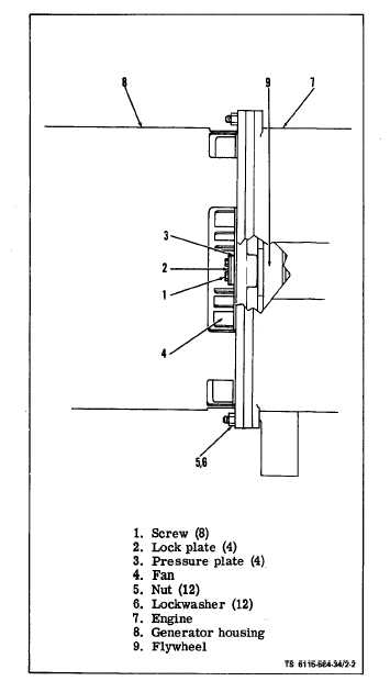
Figure 2-2. Disconnecting Engine from Generator
(b) Remove center plug from grille on blower
housing. Refer to Operator and Organizational
Maintenance Manual.
(c) Using a 5/8” socket wrench on hex head
capscrew at center of blower wheel, rotate engine
clockwise until one of the four sets of screws (1,
figure 2-2) attaching generator fan (4) and coupling
plate to engine flywheel is accessible thru opening in
generator housing (8). Straighten locking tabs and re-
move the two screws (1) and the locking plate (2)
and pressure plate (3).
(d) Rotate engine an additional 90° and remove
second set of screws. Continue until all four sets of
screws (1) are removed.
(e) Remove twelve nuts (5) and lockwashers
(6) attaching generator housing (8) to engine (7).
(11) Remove four screws (3, figure 2-3), lock-
washers (5), flatwashers (4) and nuts (6) attaching
each engine mount (2) to skid-base (7). Lift engine
free of Generator Set.
b. Installing Engine-Generator Assembly.
(1) Attach generator to engine.
(a) Install two 1/4- 20 x 2 in. pilot studs into
the engine flywheel (9, figure 2-2) in two holes that
are 180° apart.
(b) Align fan (4), adapter plate and flywheel (9)
using pilot studs.
(c) Install four screws (l), locking plate (2),
pressure plate (3) attaching fan and adapter to fly-
wheel (9).
(d) Remove pilot studs and install remaining
screws (l), locking plates (2) and pressure plate (3).
(e) Bend locking plates (2) to lock all screws
(l).
(f) Install twelve nuts (5) and lockwashers (6)
to attach generator housing (8) to engine (7).
(2) Lift engine generator assembly into place on
skid-base and install screws (3, figure 2-3), lock-
washers (5), flatwashers (4) and nuts (6) to attach
engine mounts to skid-base.
(3) Attach engine speed control (3, figure 2-1) to
bracket (5) and tighten nut (l).
(4) Refer to Operator and organizational
Maintenance Manual and proceed as follows:
(a) Install generator screen-guard if previously
removed.
(b) Install fuel tank.
(c) Connect oil drain hose to mounting on skid-
base.
(d) Connect fuel lines to fuel filter and fuel
injection pump.
(e) Install air filter assembly.
(f) Reconnect previously tagged wire harness
to engine (see schematic figure 1-1).
-
(g) Connect cables to starter.
(h) Install batteries and reconnect.
2-14