TM 5-6115-584-34
NAVFAC P-8-622-34
TO-35C2-3-456-2
TM-0568C-34
Table 9-1. Test Schedule
Test
Instrument
Test Method (MIL-STD-705)
513. lC
Record only the readings of the master
and panel instruments at no-load, 50%
and 100% of rated load. Record the
readings of the master and panel in-
struments at all voltage connections.
c. Test Procedure.
(1) Position switches as follows:
(a) Master switch-stop.
(b) Panel light switch-off.
(c) S1-closed.
R e q u i r e m e n t s
Accuracy shall be as follows:
Current indicator system, 10% max.
Voltage indicator system - Initial
accuracy 2.5% of full scale except that
within the ranges of 115 to 125 and 200
to 250V. The error shall not exceed 3
and 5 volts respectively.
Frequency indicator system 0.5%
maximum.
Voltage adjust range shall be between
197.6 and 218.4V for the 120/208V, 3
phase 4 wire connection between 114
and 125V for the 120V, 1 phase, 2 wire
connection between 228 and 252V for
the 120/240V, 1 phase, 3 wire connec-
tion.
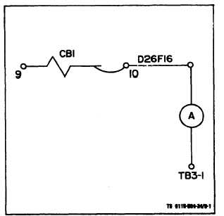
Figure 9-1. Adjusting R3 Resistor
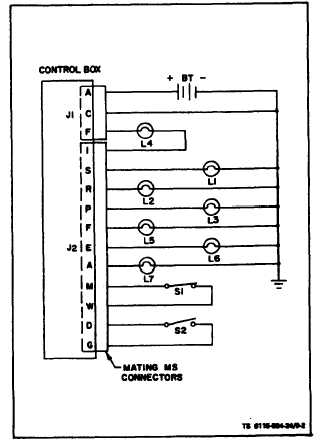
Figure 9-2. Testing Engine Control Circuitry
9-2