TM 5-6115-584-34
NAVFAC P-8-622-34
TO-35C2-3-456-2
TM-0568C-34
CR1
v
CR4
TI
<
CONNECTION
DIAGRAM
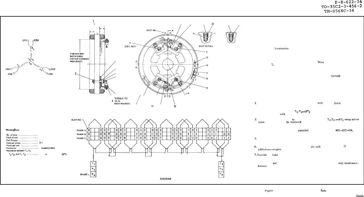
Wmdmg Oata:
\
II
9
20
2!
\ 1“1
.88 MAX
.88 MAX ~
3
4
TORQUE TO
15-20
2
5
INCH POUNDS
6
7
\
SECTION A-A
:::::::.s
/
/
132’33\
8
12-15
12
13
10
14
36
1-4
24
21
11
1 strand of ,mem 19
0.677 + 0.067 ohms at 25°C
.22
20
23
ti
7
SLOT DETAIL FOR
BALANCING
SCALE: 2/1
SEE NOTE 6
I
-,
d
u
Y
B
P H A S E A T,
PHASE B T5
PHASEL
T3
WINDING OIAGRAM
Legend
1. Laminatlorl assembly
2. Nut and washer assembly
3. Insulator
4. Bushing
5. Washer
6. Screw
7. Washer
8. Nut
9. Diode
10. Diode
11. Heat sink
12. Sleeving
13. Heat sink
14. Grommet
15. Wire
16. Splices
17. Insulation sleeving
18. Insulation sleeving
19. Wire (# 17 AWG magnet)
20. Wedge
21. Wedge
22. Slot insulation
23. Sheet
24. Insulating varmsh
25. Solder
NOTES
1, Winding extensions (item 19) shall be insulated with sleeving (Item 18) from slots
to splices.
2. Connect winding extensions T4, T5 and T6 together using splice (item 16). Splice
shall be insulated with sleeving (item 17).
3. Connect 2 leads (item 15) to each winding extension Tl, T2and T3usings!Jhce
(,tem 16). Splices shall heinsulated with sleeving (item 17). Solder leads (item 15)
to diodes (items 9 & 10) as shown in connection diagram.
4. All splices (item 16) shall be ,nstalled in accordance with MIL-STD-454, Re-
quirement 19.
5. Leads and end turns shall be tied on both ends with sleeving (item 32) at approxi-
mately every other slot.
6. Exciter rotor assembly shall be within .5 oz-inch of static balance. ff required,
add balance we]ghts (item 23) in slots. See slot detail for balancing.
7, Varmsb and bake in accordance with flawing No. 72-5243-1 (item 24). Outside
diameter of laminations, shaft hole, and surfaces under insulators (item 3) shall
be free of varnish. Varnish on outside diameter of laminations shall be free of
protruding mr bubbles and other surface irregularities which may.cause inter-
ference with rotation.
Figure 8-4. Exciter Rotor Assembly Winding Data
8-9/(8-10 blank)