T M 5 - 6 1 1 5 - 5 8 4 - 34
NAVFAC P-8-622-34
T O - 3 5 C 2 - 3 - 4 5 6 -2
TM-0568C-34
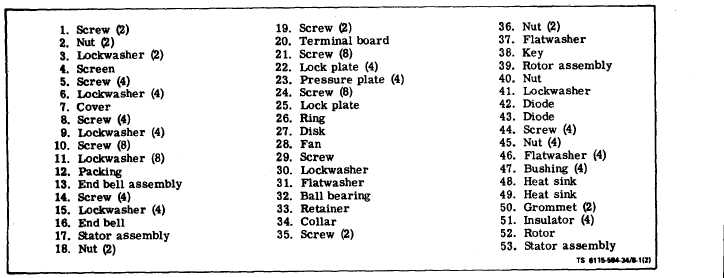
Figure 8-1. Generator Exploded View (Sheet 2 of 2)
c. Disassembly (see figure 8-l).
(1) Remove screws (l), nut (2), lockwasher (3),
attaching screen (4) to generator and remove screen.
(2) Remove screws (5), lockwashers (8), attaching
end bell cover (7) to end bell and remove cover.
(3) Remove screws (8) and lockwashers (9) hold-
ing bearing retainer (33) to the end bell (16). Remove
screws (10) and Iockwashers (11) attaching end bell
assembly (16) to stator assembly and remove end bell
assembly.
(4) Remove "O" ring (12) from bearing housing.
Remove and tag wiring harness from terminal board
(20). Remove screws (19) and nuts (18) attaching ter-
mtnal board to exciter stator and remove terminal
board.
(5) Remove four screws (14) and lockwasher (15)
attaching exciter stator (17) to end bell (16) and re-
move exciter stator.
(6) Remove eight screws (24) attaching coupling
disk (37) to rotor shaft and remove coupling, lock
plate (25) and retaining ring (26).
(7) Remove generator fan (28) which is now free.
Do not remove balance screw from fan (28).
(8) Remove rotor assembly from stator assembly
(53).
(9) Remove screw (29), lockwasher (30) and flat-
washer (31) attaching bearing (32) to rotor shaft and
remove bearing, bearing retainer (33) and shaft collar
(34).
(10) If necessary, remove diodes from rotor as
given in paragraph 8-2a above.
D o n o t r e m o v e e x c i t e r r o t o r f r o m r o t o r
s h a f t
u n l e s s
t e s t
r e s u l t s
i n d i c a t e
n e e d f o r r e p l a c e m e n t.
d. Inspect. Visually inspect windings and lead con-
nections. Check that diodes are securely mounted on
heat sinks. Clean dust, dirt, and grease from diodes.
Clean windings and drain holes. Check that end bear-
ing is not damaged or worn. Inspect cooling fan and
coupling for damage.
e. Testing Exciter Stator (Field) (High Potential
T e s t ) .
-
Observe safety regulations. The voltages used
in this test are dangerous to human life. Con-
tact with the leads or the windings under test
may cause severe, and possibly fatal, shock.
Arrange the high voltage leads so that they are
not in a position to be accidentally touched.
Keep clear of all energized parts. Always re-
duce the test voltage to zero and ground the
winding under test before making any mechan-
ical or electrical adjustments on the equip-
ment. When grounding out windings which have
been tested, always connect the connection
wire to ground first, and then to the winding.
Never perform this test without at least one
other person assisting. Generator frame shall
be securely grounded.
(1) General. The high potential test is performed
to determine whether or not the insulation of the
equipment under test is defective. It is customary to
determine whether electrical equipment will withstand
normal voltage stresses by means of a test in which
higher voltages than normal are applied for a definite
Change 5
8-3