TM 5-6115-584-34
NAVFAC P-8-622-34
TO-35C2-3-456-2
TM-0568C-34
(3) Mount injector in a suitable holding fixture.
(4) Assemble valve (7) and nozzle (9) and install
on body (15).
(5) Install nozzle cap nut (12) loosely.
When tightening nozzle cap nut & not contact
nozzle valve (7).
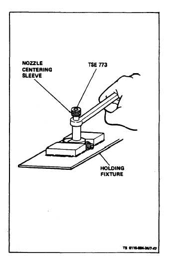
(6) Place centering sleeve TSE 773 over nozzle
for initial tightening. Remove centering sleeve after
initial tightening to prevent it from binding between
nozzle and cap nut and tighten nozzle cap nut to 50 to
55 ft-lbs.
(7) Adjust opening pressure of nozzle (see para-
graph 7-20c).
i. Installation.
(1) Make sure old gasket material has been re-
moved from injector.
(2) Assemble new nozzle gasket (5, figure 7-45),
adapter (6), gasket (7), heat shield (8) and gasket (9)
on injector (4).
(3) Install injector and assembled parts into cyl-
inder head (10).
(4) Install retaining flange (3) and tighten down
with screws (1) and washers (2).
(5) Reconnect fuel lines as described in para-
graph 7-2.
(6) On ASK equipped generators, refer to Operator and
Organizational Maintenance Manual and replace right panel
assembly.
Figure 7-47. Centering Sleeve Installation
7-44
Change 6


