TM 5-6115-584-34
NAVFAC P-8-622-34
TO-35C2-3-456-2
TM-05862C-34
NOTE
A fuel inlet stud can be fabricated with a 1/4 “-18
NPT pipe die. High pressure tubing must be
used between the Nozzle Test Stand and the
pump assembly.
NOTE
Always check to make sure that all external con-
nections are tight and that the Nozzle Test Stand
is in good order.
(8) Slowly operate the Nozzle Test Stand until a
pressure of 400 psi is achieved. A rapid drop in pressure
indicates that a leak is present. The pressure must remain
above 250 psi for at least 30 seconds.
DO NOT EXCEED A PRESSURE OF 400 PSI.
(9) Visual inspection should be as follows:
(a) Check for leakage by the head locating screw
(13, figure 7-34).
(b) Slight leakage by control unit shaft is normal
and is necessary to lubricate shaft. Fuel leakage between
the control unit body (4) and pump housing (6) indicates
that either the “O” ring (33 ) is damaged or the mating
surfaces are damaged. Replace the “O” ring (33 ) and re-
test the pump. If fuel leakage is excessive at control unit
shaft or continues past “O” ring (33) replace defective
parts.
(c) Check for leakage of fuel around the face gear
(28 ). If leakage is evident, disassemble pump and inspect
“O” ring (19).
(d) Check for fuel leakage between top of housing
and head flange. To correct, disassemble and replace
upper hydraulic head “O” ring (18).
f. Install (Method 1).
(1) Turn engine flywheel to the port closing mark
(PC) on the front cylinder (closest to blower wheel) com-
pression stroke (see figure 7-44 ).
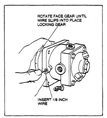
(2) Remove timing hole screw located on pump
mounting flange (figure 7-42). Insert a 1/8 inch diameter
wire into the hole.
(3) Rotate pump face gear until wire slips into place,
locking the gear in position.
(4) Mount pump on crankcase (see figure 7-32) (be
sure shims (5) are in place) and secure in position using
four hexagon nuts (2), flatwashers (4) and Iockwashers
(3). If “O” ring seal between pump and crankcase is worn,
cracked or otherwise defective, replace it.
(5) Remove wire. Install timing hole screw and
copper gasket.
Figure 7-42. Injection Pump Installation
g. Install (Alternate Method 2).
(1) If pump was not timed by method 1, time now
using alternate method 2 below.
(2) Connect flexible fuel inlet line to pump inlet.
Connect fuel return line.
(3) Connect each fuel outlet line to the proper pump
outlet (see paragraph 7-2).
(4) Connect governor linkage to governor arm.
(5) Start and run engine. Adjust governor linkage if
required (see paragraph 7-3).
A maximum trottle stop screw, located on the
injection pump control assembly, limits the max-
imum amount of fuel which can be injected into
the engine. This screw should not be tampered
with; it has been properly adjusted at the factory
to protect the engine from over-fueling (see
figure 7-33).
h. Adjust/Time on Equipment.
(1) Time the injection pump to the engine by using
the proper thickness timing button between pump plunger
and tappet (see figure 7-33). Use method 1 when replacing
an old pump if the port closing dimensions and bottom
number of the old pump were recorded. Use method 2 if
the dimensions are lost, an old pump is being timed, or
when replacing either the camshaft or crankshaft.
7 - 3 8
Change 5