TM 5-6115-584-34
NAVFAC P-8-622-34
TO-35C2-3-456-2
TM-05682C-34
(20) Place pump in horizontal position with control
unit bore (36) facing up.
(21) Center the plunger sleeve (34) in the control
unit bore (36). Position plunger sleeve pin (5) so that the
flats align with the groove in the control sleeve (34) and
the electric pencil mark (dot) faces the top of the pump.
(22) Insert control unit assembly (4) into housing
(6), pressing gently until control unit seats.
Do not use force. If flange is not seated on pump
housing, rotate arm both ways with finger pres-
sure control unit in.
NOTE
Rotate the control unit lever through a 360° arc
to make certain that the control unit assembly
is correctly installed. Failure to rotate 360°
indicates that the plunger sleeve pin (5) is not
engaging the plunger sleeve slot.
(23 ) Install control unit assembly retaining plate, as
shown in figure 7-39 using two tab washers and two
screws. Torque screws to 20-25 inch-pounds and bend
locking tabs over screws.
NOTE
If control unit will not seat, pull it out and re-
peat steps (20 ) through (22).
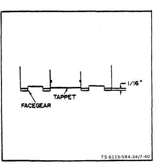
Figure 7-40. Checking Plunger Sleeve Alignment
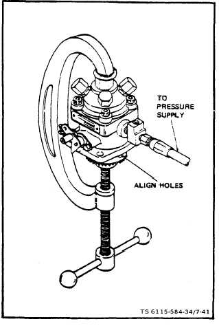
Figure 7-41. Pressure Testing Injection Pump
e. Test.
(1) Turn pump upside down and depress tappet
with thumb. Tappet should recede 1/16” into face gear
(figure 7-40). If tappet cannot be depressed 1/16” into
face gear, plunger sleeve pin (5, figure 7 -34) is improperly
aligned. Disassemble pump and re-align pin.
(2) Remove the overflow valve assembly from the
fuel outlet hole in the pump housing. Install a 1/4” pipe
plug into the fuel outlet hole.
(3) Secure the pump close to a Nozzle Test Stand.
(4) Cap outlet ports (see figure 7-41).
(5) Install C-clamp on injection pumps as shown in
figure 7-41 to retain face gear.
(6) Align holes in face gear and housing (see figure
7-41).
(7) Connect the Nozzle Test Stand to the fuel inlet
hole in the pump housing.
7-37