T M 5 - 6 1 1 5 - 5 8 4 - 34
NAVFAC P-8-622-34
T O - 3 5 C 2 - 3 - 4 5 6 -2
TM-0568C-34
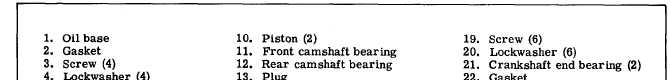
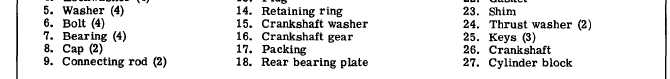
Figure 7-15. Crankshaft Pistons and Connecting Rod (Sheet 2 of 2)
NOTE
The connecting rod and cap are stamped for
installation in the proper cylinder. When re-
moving piston assemblies, check the marking
so each piston can be installed in the proper
cylinder.
b. Removal (see figure 7-15).
(1) Drain crankcase oil and remove oil base (1)
and gasket (2) by removing screw (3), lockwasher (4)
and washer (5).
(2) Remove oil cup assembly (10, figure 7-19).
(3) Remove cylinder head (paragraph 7-9) and
remove all carbon at the top of the cylinder bore. Re-
move ridge from cylinder bore before removing
piston.
(4) Remove bolts (6, figure 7-15), cap (8) and
bearings (7) from each connecting rod (9) and push the
piston assembly (10) upward through top of cylinder
bore with a soft wooden tool to prevent rod bearing
damage. Loosely install cap (8) and bearings (7) on
the corresponding removed piston assembly to main-
tain proper grouping.
c. Disassembly (see figure 7-14).
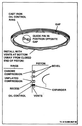
(1) Using a ring expander, remove piston rings
(1, 2 and 4) and oil ring expander (3) from each piston.
(2) Remove two retaining rings (5) and push piston
pin (6) from each piston.
d. Inspect and Repair.
(1) Pistons. Thoroughly clean and inspect each
piston. Clean carbon from ring grooves and be sure
all oil holes are open. If any piston is badly scored
or burred, loose in cylinders, has badly worn ring
grooves or otherwise is not in good condition, replace
it. Check the piston clearance in cylinder 90° from
axis of piston pin and below oil control ring (4, figure
7-14). Clearance should be 0.0062 to 0.0082 inch (see
table 1-2). If not, replace piston and check cylinder
wall for possible reconditioning.
(2) Piston Pins. Each piston pin should be a
thumb push fit into its piston at room temperatures.
Figure 7-16. Piston Ring Installation
7-17