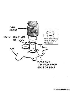
Be careful not to cut into counterbore bottom. See
figure 7-12. Thoroughly clean valve seat counterbore
and remove any burrs from the edges. Drive new valve
seat inserts into place. Be certain that each seat rests
solidly on bottom of counterbore at all points. To
make installation easier, heat cylinder head in an oven
at 325 °F (163 ºC) for about l/2-hour. Face each new
seat to the value given in table 1-2. The finished seat
face should contact approximately center of the valve
face. Use Prussian Blue on each valve face to check
this. Make any corrections on the seat, not the valve
face. When new seats are installed and faced, insert
valve into each seat and check clearance from valve
head to the face of cylinder head. If it is not the value
given in table 1-2, regrind the seat.
(4) Valve Springs. Check valve springs (5, figure
7-11) on a compression scale. Valve spring data is
given in the table 1-2. Replace any spring that is weak,
cracked or pitted or has ends out of square.
(5) Push Rods. Check that push rod is absolute-
ly straight. Replace bent or worn push rods.
e. Reassemble.
(1) Push a valve stem oil seal assembly (4) onto
each intake valve guide (6, figure 7-11). Then oil inside
surface of each seal.
(2) Oil the stem of each valve (8 and 10, figure
7-11) and insert each in its own guide (6 and 9). If in-
take valve (8) is removed with seal in place on guide,
wrap sharp edge of valve notch with cellophane tape
to protect seal bore.
(3) Check each valve for a tight seat.
(4) Using a valve spring compressor (see figure
7-10), compress each valve spring and insert the valve
spring retainer (3, figure 7-11) and retainer locks (2).
Install valve rotator (l).
f. Install (see figure 7-9).
(1) Place head assembly (8) and gasket (10) on
cylinder block (9). Install springs (18), washers (19)
and packings (16) on push rod shields (17) and install
assembled push rod shields in cylinder block. Lift
back side of cylinder head and place push rod shields
in place, lower cylinder head in place. Use an anti-seize
compound on head bolt threads and thread bolts (4
and 6) and washer (7) into cylinder block (9).
Do not tighten head bolts at this time.
(2) Refer to Operator and Organizational
Maintenance Manual and install intake manifold. Tor-
que bolts 13-15 ft-lbs (see table l-l). Bend over lock
tabs. Now tighten head bolts 44 to 46 ft-lbs (see table
1-1) following the sequence in figure 7-13.
TM 5-6115-584-34
NAVFAC P-8-622-34
TO-35C2-3-456-2
TM-05682C-34
Figure 7-12. Valve Seat Replacement
(3) Refer to Operator and Organizational
--
Maintenance Manual and install mufflers.
Install push rod with longer shouldered
end toward rocker arm. Improper installa-
tion causes push rods to bend or break.
(4) Install push rods (15, figure 7-9), rocker arms
(3), rocker arm balls (2) and rocker arm nuts (l).
(5) Set valve clearance per Operator and
Organizational Maintenance Manual.
(6) Refer to Operator and Organizational
Maintenance Manual and install air shutter assembly
and shroud assembly.
NOTE
After the first 50-hours of operation, read-
just valve clearance.
7-10. PISTON AND CONNECTING ROD.
a. General (see figure 7-14). Each piston (7) is fit-
ted with three compression rings and an oil control
ring (4). Full floating piston pins connect the piston
to the connecting rod. The pins are held in place with
retaining ring (5) at each end. The lower end of each
connecting rod contains half shell precision bearings
(11) and the upper end contains reamed bushings (13).
Change 5
7-13