TM 5-6115-584-34
NAVFAC P-8-622-34
TO-35C2-3-456-2
TM-0568C-34
7-8.BATTERY CHARGE ALTERNATOR.
a. Inspect (eee figure 7-7).
(1) Refer to Operator and Organizational
Maintenance Manual and remove blower housing.
(2) Check stator wiring and voltage regulator
wiring for loose connections or shorts. Check fuse F1
(16).
b. Test on Equipment.
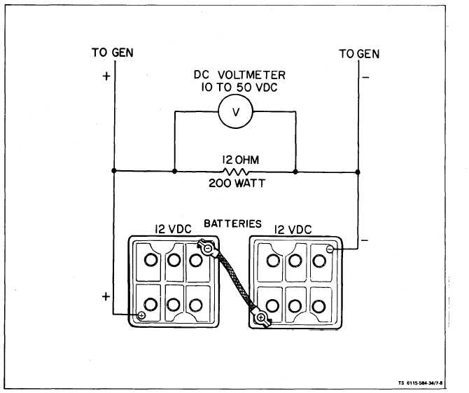
(1) Load the batteries with a 12 ohm, 200 watt
resistor (see figure 7-8). Run the set at 60 Hz, 1800
RPM. The charge rate should be between 6.5 and 10
(2) With generator running (60 Hz), disconnect
batteries leaving 12 ohm resistor load in circuit to
generator. The alternator should provide a dc voltage
between 24 and 28.5 volts.
c. Removal.
( 1 ) R o t o r.
R e f e r t o O p e r a t o r a nd
Organizational Maintenance Manual and remove the
blower housing. Remove blower wheel assembly (4,
figure 7-7) per paragraph 7-7. Remove rotor mounting
screws (9) and lockwashers (10) attaching rotor(11) to
blower wheel (4) and remove rotor (11).
(2) Stator. Disconnect stator leads (14, figure
7-7) from terminal block on engine back plate. Re-
move wire clamp from oil filter casting. Remove
screws (12) and lockwashers (13) attaching stator (15)
amperes.
to engine and remove stator (15).
Figure 7-8. Resistively Loading the Batteries
7 - 8