T M 5 - 6 1 1 5 - 5 8 4 - 3 4
N A V F A C P - 8 - 6 2 2 - 3 4
T O - 3 5 C 2 - 3 - 4 5 6 - 2
T M - 0 5 6 8 C - 3 4
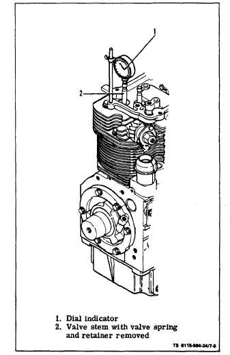
Figure 7-5. Measuring Top Dead Center
7-5. FLYWHEEL HOUSING.
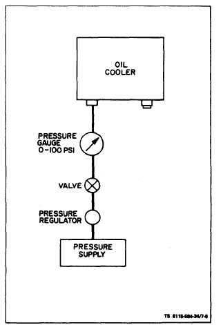
Figure 7-6. Testing Oil Cooler
c. Test (see figure 7-6).
(1) Plug the oil cooler outlet using suitable plug.
a. Remove flywheel per paragraph 7-4. Remove
flywheel housing (see figure 7-3). Remove screws (6),
(2) Connect the oil cooler in suggested test set-
lockwashers (7) and washers (8) while supporting
up (see figure 7-6).
housing (5). Remove flywheel housing.
b. Clean and Inspect. Inspect flywheel housing for
cracks or dents. Wipe interior of housing with clean
cloth. Check to see that pointer is not bent and se-
curely mounted.
c. Install. Mount flywheel housing (5) to the engine
using screws (6), lockwashers (7) and washers (8).
7-6. OIL COOLER.
a. Remove. Refer to Operator/Crew and Organiza-
tional Maintenance Manual and remove oil cooler.
b. Clean and Inspect. In a suitable area clean oil
cooler using a brush and fuel oil. Inspect for leaks,
bent fins and/or bad inlet and outlet threads.
(3) Apply 25 psi air pressure to the oil cooler.
(4) Close the valve and monitor the pressure. A
drop in air pressure indicates a leak in the oil cooler.
7-7. BLOWER WHEEL ASSEMBLY.
a. Inspect (see figure 7-7).
(1) Refer to Operator/Crew and Organizational
Maintenance Manual and remove blower housing.
(2) Check blower wheel (4) for cracks or broken
fins. Check for free play between blower wheel and
hub. Replace torsion damper assemblies (6) if free
play is present.
7 -6