e. Replace. Using screws (13, figure 7-2), lock-
washers (14), and nuts (15), attach governor control
bracket (12) to engine back plate. Attach speed control
cable (11) to governor arm (3) with pin (6) and cotter
pin (5). Attach governor arm (3) and governor linkage
(1) between governor and fuel injection pump (2). If
new ball joints are used on linkage, position the new
joints to obtain the same length or 1/32 inch more (1
turn = 1/32 inch) than the old linkage. If old linkage
length is not available, position new ball joints about
midway on each end linkage, then lengthen 1/8 inch.
Do not overspeed engine for more than a
moment.
Start engine and adjust speed control for 61.5 Hz output at no load.
It should then be possible to move the entire linkage down 1/2 inch
with a light finger pressure. If not, adjust linkage 1 turn at a time until
1/2 inch downward travel is obtained. It should then be possible to
momentarily lift the linkage 1/2 inch with unit operating at rated load.
Balance up and down travel by adjusting length of the linkage. On
ASK equipped generators, refer to Operator and Organizational
Maintenance Manual and replace right panel assembly.
7-4. FLYWHEEL AND RING GEAR ASSEMBLY.
a. Removal (see figure 7-3).
(1) Remove engine from set per paragraph 2-9.
(2) Remove timing pointer (10, figure 7-3) by re-
moving screws (11).
(3) The flywheel (1) is a tapered fit on the
crankshaft (2). Remove flywheel mounting screw (3)
and washer (4). Support and remove flywheel and ring
gear assembly by using a two pronged wheel puller
inserted through the slots provided in the flywheel.
b. Clean and Inspect. Clean the flywheel and ring
gear assembly (1) using solvent. Check the ring gear
for broken or worn teeth.
c. Install. Replacement flywheels are supplied with
timing marks already stamped in place. The engine
must still be timed properly to this timing mark. The
only accurate method of determining the port closing
point is to measure piston travel. This is a critical
measurement and should be done only with accurate,
dependable equipment. Mount flywheel keying
properly and tighten in place using screw (3) and
washer (4), (figure 7-3). With the flywheel mounted,
rotate flywheel counterclockwise until Number 1
cylinder is on its compression stroke, which follows
the closing of its intake valve. Remove the exhaust
rocker arm (3, figure 7-9), exhaust valve rotator (1,
figure 7-11), valve looks (2), spring retainer (3) and
spring (5). using fabricated tool (see figure 7-10).
Allow exhaust valve to drop down onto top of piston.
Rotate flywheel counterclockwise until piston is at
TM 5-6115-584-34
NAVFAC P-8-622-34
TO-35C2-3-456-2
TM-0568C-34
NOTE
As the piston comes up to Top Dead Center
there is very little change in the dial indicator
reading and extreme care should be used to
establish the exact Top Dead Center.
Zero the dial indicator. Rotate flywheel in opposite
direction (clockwise) to a point where the dial indica-
tor will indicate approximately 0.200 inch. Rotate fly-
wheel counterclockwise slowly until dial indicator
shows 0.128 inch before Top Dead Center. Care must
be taken to insure that the valve is following the piston,
and that reading is accurate. This procedure must be
followed to insure that all slack is taken out of the
piston and connecting rod fits. At 0.128 inch before
Top Dead Center position, check timing pointer in
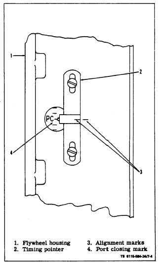
timing port on side of flywheel housing (5, figure 7-3).
The timing pointer (10) should be in exact alignment
with P.C. mark on flywheel. If pointer is not in align-
ment, move pointer, and remark generator adapter
as shown in figure 7-4. Destroy old alignment mark.
Figure 7-4. Timing Port and Port Closing Mark
Top Dead Center. This can be measured on top of
exhaust valve stem with a dial indicator (see figure 7-
5).
Change 6 7 -5