TM 5-6115-584-12
NAVFAC P-8-622-12
TO-35C2-3-456-1
TM-05682C-12
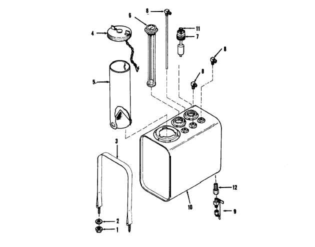
1. Nut (4)
9. Drain valve
2. Flatwasher (4)
6. Fuel gauge
10. Fuel tank
3. Srap (2)
7. Float switch
4. Filler cap
11. Connector
8. Fitting (3)
5. Strainer
18. Adapter
TS 6115-584-12/4.7
Figure 4-7. Fuel Tank Assembly
(4) Fuel Level Gauge. Engage threads of fuel
(3) Check. that drain valve is closed before filling
level gauge (5) 1/2 turn into tank (9). Coat threads
tank with proper grade of fuel.
with sealing compound MIL-S-22473. Tighten float
level gauge into tank using tools only on hex portion
NOTE
of gauge. Install filler cap (4) and strainer (5) into tank
After each time fuel filters or strainer is
(9).
drained or elements replaced, purge air from
g. Installation.
fuel system by moving master switch on con-
trol panel to PRIME & RUN position. This
(1) Install straps (3) onto the skid-base and se-
should activate the fuel transfer pump and
cure with nut (1) and flatwasher (2) on inside of skid-
force trapped air back to the vented fuel tank.
base only.
4-20. FUEL FILTER ASSEMBLIES AND STRAINER
(2) Position fuel tank assembly onto skid-base.
ASSEMBLY<
position straps over tank assembly and secure with
There are two identical fuel filter assemblies (see
nut (1) and flatwasher (2).
figure 3-13), one which acts as the primary and the
4-17