TM5-6115-584-12
NAVFAC P-8-622-12
TO-33C2-S-4S6-1
TM-05682C-12
(2) Install power unit assembly (6) into shutter
assembly box (32) using screws (4) and special washer
(5). Mount connector (3) using screws (1) and nuts (2).
(3) Shutters. Mount torsion spring (16) using nut (14)
and washer (15). Mount shutters using screws (7) and
washers (8). Ensure that adequate clearance between
shutter and shutter box sides is maintained and that
brackets (12) are seated againat shoulder of bearing (17)
prior to tightening Screws (7). Check shutter to ensure
they will fully open and close without binding.
g. Adjustments.
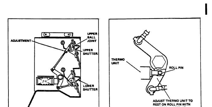
(1) Shutters (see figure 4-5). Disconnect ball
joint from upper shutter. Adjust ball joint until upper
shutter closes tightly on lower shutter when lower
shutter is held closed. Re-attach ball joint to upper
shutter.
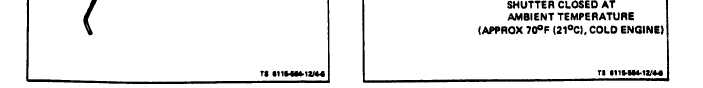
(2) Thermo Unit be figure 4-6). With Generator
Set at 70° F, (21°C) loosen thermo unit guide mounting
screws, the mounting holes in the shutter box are
slotted. Slide the assembly to a position where the
thermo unit plunger rests on roll pins with shutters
closed. Tighten mounting screws.
h. Installation (see.figure 3-17).
(1) Install oil cooler and base as described in
paragraph 4-28. Install shroud (36), clip (35) and screw
(33).
(2) Blower Housing. Install blower housing (32)
on engine using screws (30 and 31).
(3) Blower Grille Assembly. Install grille (29)
on blower housing (32) using screws (26) and re-
tainers (27). (For units without ASK.)
(4) Baffles and Shrouds. Install shroud (22) using
screws (15 and 17) and washer (16). Install rear shroud
(36) using screw (33), clip (35) and screw (34). Install
baffle (25) with hook bolt (24) and nut (23).
(5) Shroud Assembly. Install door panel (12) and
shroud (11] as an assembly to the engine and blower
housing (32) using screws (7) and washers (8). Close
latches (14).
(6) Shutter Assembly. Install shutter assembly (4)
on engine and blower housing (32) using capscrews (3).
Connect connector plug to thermo unit connector
receptacle (5).
(7) Air Housing Duct Cover. Mount air housing
duct cover (2) to shutter assembly (4) using screws
(1). Connect air intake hose to duct cover using hose
clamp (6).
(8) On ASK equipped generators, refer to para 5-3
and 5-8 and replace ASK cover assembly and exhaust
plenum.
Figure 4-5. Adjusting Shutters
Figure 4-6. Adjusting Thermo Unit
Change 7
4-15