8-13.
a.
—
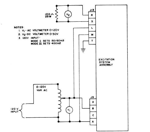
ME 6115-545-34/8-19
Figure 8-19.
Excitation Assembly System Test Set-Up
Repair. Reassembly and Installation.
Repair.
(1) Relay circuit board assemblies found to be
defective during testing.
(2) Replace all defective diodes, resistors, and
transformers.
(3) Replace defective connectors.
(4) Repair or rebuilt wiring harnesses as re-
quired. See wiring schematics in Chapter 1 and
wiring harness diagrams in Chapter 5.
b. Reassembly.
(1) See figure 8-18 to reassemble the electronic
component assembly.
(2) See figure 8-16 and 8-17 to reassemble the
voltage regulator assembly.
(3) See figure 8-15 and refer to paragraph 8-11,
and reassemble the excitation system assembly in
reverse order of disassembly,
c.
Installation.
See figure 8-1 and refer to para-
gragh 8-10 to install the excitation system assembly.
8-14. Adjustments.
After the excitation system assembly is reinstalled,
perform the following operational adjustments:
a. Voltage Adjustment
—
(1) With Voltage Adjust control on generator
control panel set at approximately midpoint, start
generator set.
8-27