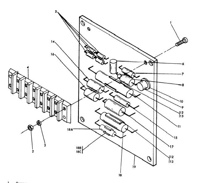
1.
2.
3.
4.
5.
6.
7.
8.
Screw
Nut
Washer
Terminal block
Semiconductor
Resistor
Resistor
Semiconductor
9.
Transistor
10.
Pad
11.
Capacitor
12.
Clip
13.
Eyelet
14.
Capacitor
15.
Resistor
16.
Resistor
17.
Resistor
18.
Capacitor
18A. Capacitor
18B. Clip
18C. Eyelet
19.
Printed circuit board
ME 6115-545-34/8-18 Cl
Figure 8-18.
Electronic Component Assembly
(b) Connect the positive output terminal (4)
(e) Slowly raise the ac power supply to
of a variable 24 Vdc power supply to the other end
37 volts rms.
The dc voltage at terminals 3 and 4
of the resistor. Connect the negative (-) terminal
shall drop sharply to below 1 volt.
of the power supply to terminal 3.
(f) For the 400 Hz electronic component
(c) Connect a variable 100 Vac power sub-
assembly, repeat steps (a) thru (e) using a 400 Hz
ply to terminals 1 and 2.
v a r i a b l e a c p o w e r s u p p l y .
(d) Adjust the dc power supply voltage to
10 volts.
8-26 Change 1