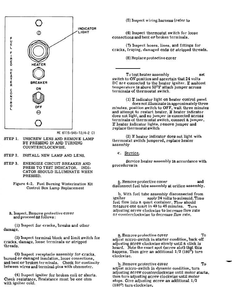
Figure 4-2.
b
. T
e
s
t
.
4 - 9 .
H e a t e r A s s e m b l y I n s p e c t , T e s t , S e r v i c e , a n d
A d j u s t .
a. Inspect. Remove protective cover
( 7 5 ,
f i g .
4 - 1 ) and proceed as follows:
(1) Inspect for cracks, breaks and other
damage.
(2) Inspect terminal block and limit switch for
cracks, damage, loose terminals or stripped
threads.
(3) Inspect receptacle assembly for cracks,
burned or damaged insulation, loose connections,
and bent or broken terminals.
Check for continuity
between wires and terminal pins with ohmmeter.
(4) Inspect igniter for broken coil or shorts.
Check resistance. Resistance must be one ohm
with igniter cold.
(5) Inspect wiring harness (refer to
p a r a -
g r a p h
3 - 1 3 9 ) .
(6) Inspect thermostat switch for loose
connections and bent or broken terminals.
(7) Inspect hoses, lines, and fittings for
cracks, fraying, damaged ends or stripped threads.
(8) Replace protective cover ( 7 5 , f i g . 4 - l ) .
To test heater assembly ( 6 1 , f i g . 4 - l ) , set
switch to ON position and ascertain that 24 volts
DC are connected to the heater igniter. If ambient
temperature is above 50°F attach jumper across
terminals of thermostat switch.
( p a r a
4 - 5 )
(1) If indicator light on heater control panel
( f i g . 4 - 2 ) does not illuminate in approximately three
minutes, position switch to OFF, wait three minutes
and attempt to restart heater. If heater indicator
does not light, and no jumper is connected across
terminals of thermostat switch, connect a jumper.
Jf heater indicator lights, remove jumper and
replace thermostat switch ( 3 9 , f i g . 4 - 1 ) .
(2) If heater indicator does not light with
thermostat switch jumpered, replace heater
assembly ( 6 1 , f i g . 4 - l ) .
c.
Service.
Service heater assembly in accordance with
procedures in t a b l e 4 - 1 .
4 - 1 0 .
F u e l
R e g u l a t o r
V a l v e
A d j u s t m e n t
( f i g .
4 - 3 ) .
a. Remove protective cover
( 7 5 ,
f i g .
4 - 1 ) and
disconnect fuel tube assembly at orifice assembly.
b. With fuel tube assembly disconnected from
ign~ter ( f i g . 4 - 3 ) apply 24 volts to solenoid. Time
fuel flow into a quart container. Flow should
measure one quart in 40 to 45 minutes.
Turn
adjusting screw clockwise to increase flow rate
or counterclockwise to decrease flow rate.
4 - 1 1 . F l a m e M i c r o - s w i t c h A d j u s t m e n t ( f i g . 4 - 4 ) .
a. Rem.we protective cover ( 7 5 , f i g . 4 - l ) . To
adj~st micro-switch in starter condition, back off
adjusting screw clockwise slowly until a click is
heard.
Note the exact spot (screw slot) that this
happens. Then give an additional 1/2 (180°) turn
clockwise.
b. Remove protective cover ( 7 5 , f i g . 4 - l ) . To
—
adjtist micro-switch in dynamic condition, turn
adjusting screw counterclockwise until motor starts,
then turn adjusting screw clockwise until motor
stops. Give adjusting screw an additional 1/2
(180°) turn clockwise.
4 - 8 C h a n g e 1