Figure 4-4.
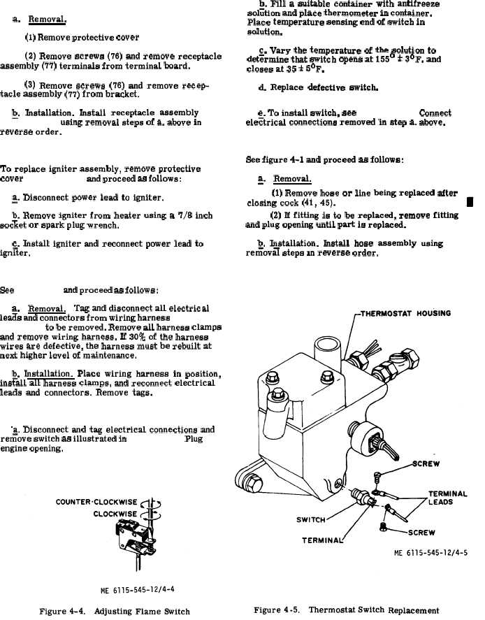
Figure 4-5.
4 - 1 2 .
R e c e p t a c l e
A s s e m b l y
R e p l a c e m e n t .
a.
Removal.
(1) Remove protective cover ( 7 5 , f i g . 4 - 1 ) .
b. Fill a suitable container with antifreeze
soliition and place thermometer in container.
Place temperature sensing end of switch in
Solutiom
(2) Remove screws (76) and remove receptacle
assembly (77) terminals from terminal board.
(3) Remove screws (76) and remove recep-
tacle assembly (77) from br~ket.
Q.
Installation.
Install
receptacle
assembly
( 7 7 , f i g . 4 - 1 ) using removal steps of a, above in
reverse order.
4 - 1 3 .
I g n i t e r
A s s e m b l y
R e p l a c e m e n t .
To replace igniter assembly, remove protective
cover ( 7 5 , f i g . 4 - 1 ) and proceed as follows:
~. Disconnect power lead to igniter.
~. Remove igniter from heater using a 7/8 inch
socket or spark plug wrench.
c. Install igniter and reconnect power lead to
ign~ter,
4 - 1 4 .
W i r i n g
H a r n e s s
R e p l a c e m e n t .
See f i g u r e 4 - 1 and proceed as follows:
a.
Removal,
Tag and disconnect all electrical
le~s and connectors from wiring harness ( 4 o r 1 1 ,
f i g .
4 - 1 ) to be removed. Remove all harness clamps
and remove wiring harness, If 30% of the harness
wires are defective, the harness must be rebuilt at
next higher level of maintenance.
b. Installation. Place wiring harness in position,
ins~all all harness clamps, and reconnect electrical
leads and connectors. Remove tags.
4 - 1 5 . T h e r m o s t a t S w i t c h T e s t i n g a n d R e p l a c e m e n t .
“a. Disconnect and tag electrical connections and
refiove switch as illustrated in f i g u r e 4 - 5 . Plug
engine opening.
c. Vary the temperature of the solution to
det~rmine that switch opens at 155° * 3°F. and
closes at 35 * 5°F.
d. Replace defective switch.
e. To install switch, see
f i g u r e
4 - 5 . Connect
ele~trical connections removed in step a. above.
4 - 1 6 . H o s e s , L i n e s , a n d F i t t i n g s R e p l a c e m e n t .
See figure 4-1 and proceed as follows:
~.
Removal.
(1) Remove hose or line being replaced after
closing cock (41, 45).
(2) If fitting is to be replaced, remove fitting
and plug opening until part is replaced.
b. Installation. Install hose assembly using
reriioval steps m reverse order.
4 - 1 0
C h a n g e
3