TM 5-6115-465-34
NAVFAC P-8-625-34
T.O. 3SC2-3-446-2
TM 06858B/06859D-34
(e) Bend the tab (point D, figure 5-5) o f
(d) Adjust carrier bushing at point (B)
bracket toward the switch until the switch actuates.
A1-A2 and C1-C2.
(f) Remove 24 Vdc, and then apply again
to insure that the switch actuates properly,
(e) Secure adjustment by tightening nuts
(l).
(g) Remove 24 Vdc and replace 0.010 inch
feeler gauge with 0.018 inch feeler gauge.
(f) Recheck for continuity at a clearance
of 0. 035 inch and for open circuit at 0. 040 inch.
(h) Apply 24 Vdc again to check that the
switch does not transfer.
(19) Adjust economizing switch as follows:
(see figure 5-5.)
(i) Readjust if necessary,
(a) Move loosely installed bracket (3) to
(20) Adjust auxiliary contacts as follows: (see
transfer switch.
(b) Check that the switch button is fully
(a) Loosen nuts (4) and position lift comb
depressed. and allow 0.010 inch clearance between
(5) so that the deflection on the guide leaf springs (6)
the switch button and the top operator (point (C)).
is nearly equal in the energized and de-energized
positions.
(c) Insert a 0.010 inch feeler gauge into
(b) Secure adjustment by tightening nuts
the core gap (point (A)).
(4).
(c) Insert a 0.018 inch feeler gauge be-
(d) Apply 24 Vdc to connector pins A and
tween the guide rod head and the operator (point E).
B (see figure 5-6).
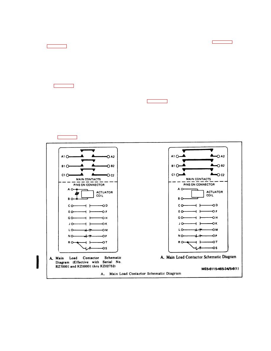
Figure 5-6. Main Load Contactor Schematic Diagram, Contactor to Load Terminals Wiring Harness,
Dwg. No: 72-2290, and Contactor to Reconnection Board Wiring Harness, Dwg. No.
72-2225 (Sheet 1 of 3)
5-9
Change 2


