T.O. 35C2-3-442-2
P-9-TM-457-35
TM 5-6115-457-34
TM-07464A-35
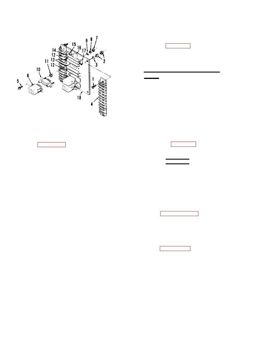
6-94. INSTALLATION. Refer to figure
6-22 and install the DC relay assembly.
Secure the assembly in position with four
nuts, then refer to figure 1-15 and recon-
nect wiring to the relay terminal board.
Replace mode I relay box cover.
6-95.
MODE I RE LAY BOX ASSEMBLY
(A27).
6-96.
ON EQUIPMENT TEST.
a. Symptom and Isolation of Malfunc-
tion. A malfunction of the mode I relay
box assembly is usually indicated by a
failure of the DC relay assembly, failure
of the engine to crank when the start-run-
stop switch S2 is energized, and unequal
F i g u r e 6-24. DC relay assembly (A5)
reactive load sharing when the generator
exploded view
set is operated in parallel. To isolate the
malfunction, refer to figure 1-14 and pro-
Legend to figure 6-24:
ceed as outlined in steps b. through d.
1.
Screw (4)
WARNING
2.
Nut assembly (8)
3.
Washer (4)
Exercise extreme care not to
4.
Terminal board (2)
touch electrical connections when
Screw assembly (6)
5.
working on the electrical compon-
6.
Relay (3)
ents with the generator set opera-
7.
Nut (6)
Lock washer (6)
ting.
8.
Washer (6)
9.
b. To isolate a malfunction of the DC
10.
Relay socket (3)
11.
relay, refer to paragraph 6-87.
Spacer
12.
Resistor (2)
NOTE
13.
Resistor (2)
14.
Resistor
Remove cover from mode I relay
15.
Silicone junction rectifier
box to gain access to the test
16.
Silicone bridge rectifier
17.
points, see figures 6-15 and
Silicone junction rectifier
18.
6-22.
Board
Change 1
6-66


