T.O. 35C2-3-442-2
P-9-TM-457-35
TM 5-6115-457-34
TM-07464A-35
and carefully remove cotter pin (1). Slide
4-25. INSTALLATION. Refer to Operator
rod (3) free of block (4), Remove nut (5),
and Organizational Maintenance Manual and
lock washer (6) and screw (7) retaining
install control assembly.
block (4) to control bar (12).
SHUTTER.
4-26.
b. Remove closing spring (8) and un-
screw spring studs (9) free, from left angle
4-27. REMOVAL. Refer to Operator and
(21).
Organizational Maintenance Manual and
remove shutter.
c. Carefully remove retaining rings (10).
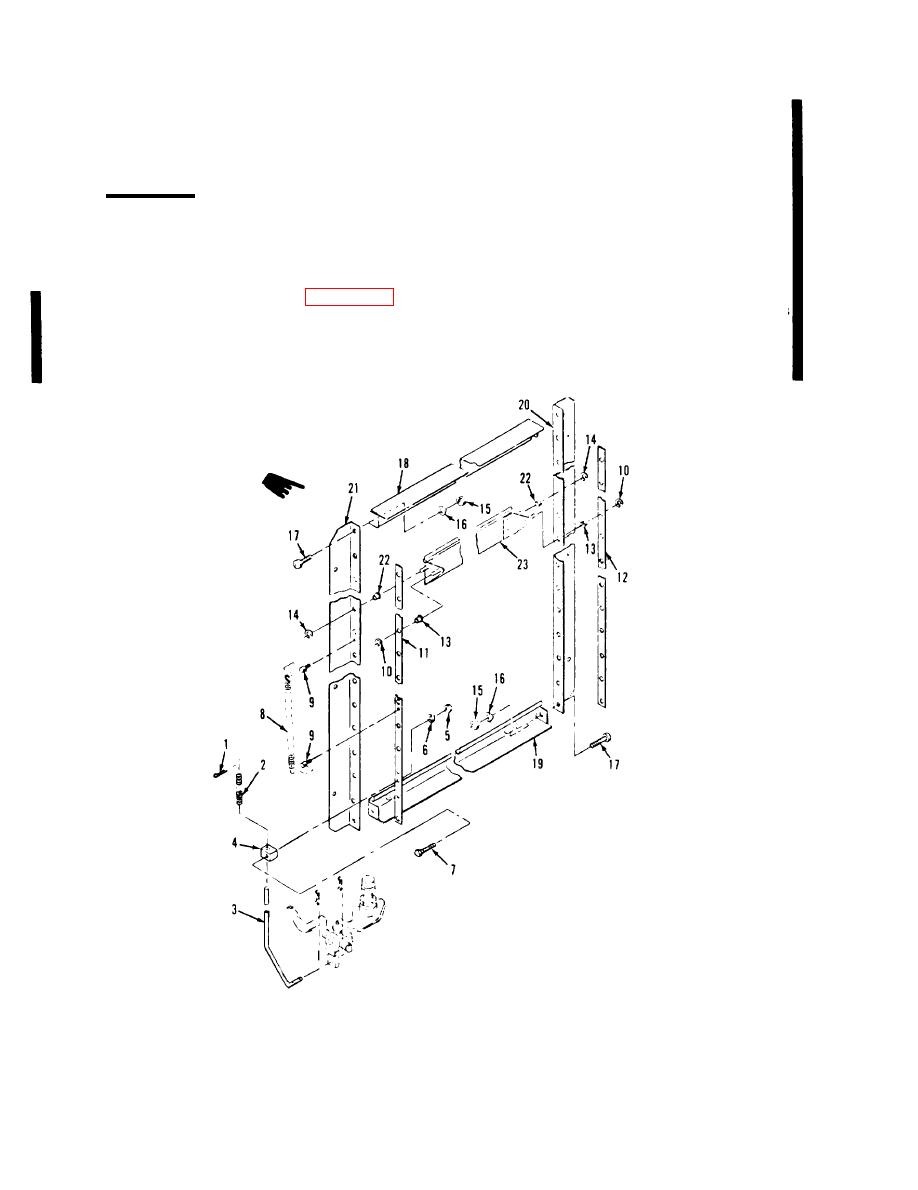
4-28. DISASSEMBLY. Refer to figure 4-3
Slide control rods (11) and (12) clear of vanes
and disassemble the shutter as follows:
(23). Remove bushings (13) from control
bars (11 and 12). Carefully remove re-
a. Place shutter face down on a clean,
taining rings (14).
dirt-free work bench. Secure spring (2)
Figure 4-3. Shutter, exploded view
Change 1
4-6


