P-9-TM-457-35 T.O. 35C2-3-442-2
TM-07464A-35 TM 5-6115-457-34
4-22. INSPECTION.
a. Inspect threads for damage and parts
for cracks.
b. Inspect shaft for nicks, burrs, and
scoring in flange bushing area.
c. Inspect flange bushing for nicks,
scores, and out of roundness.
d. Inspect springs for distortion and
broken ends.
e. Test power element for proper
operation, refer to Operator and Organiza-
tional Maintenance Manual.
f. Inspect manual control handle for
distortion.
4-23. REPAIR.
a. Remove nicks and burrs using a file
or stone.
b. Straighten distorted manual control
handle using suitable tools.
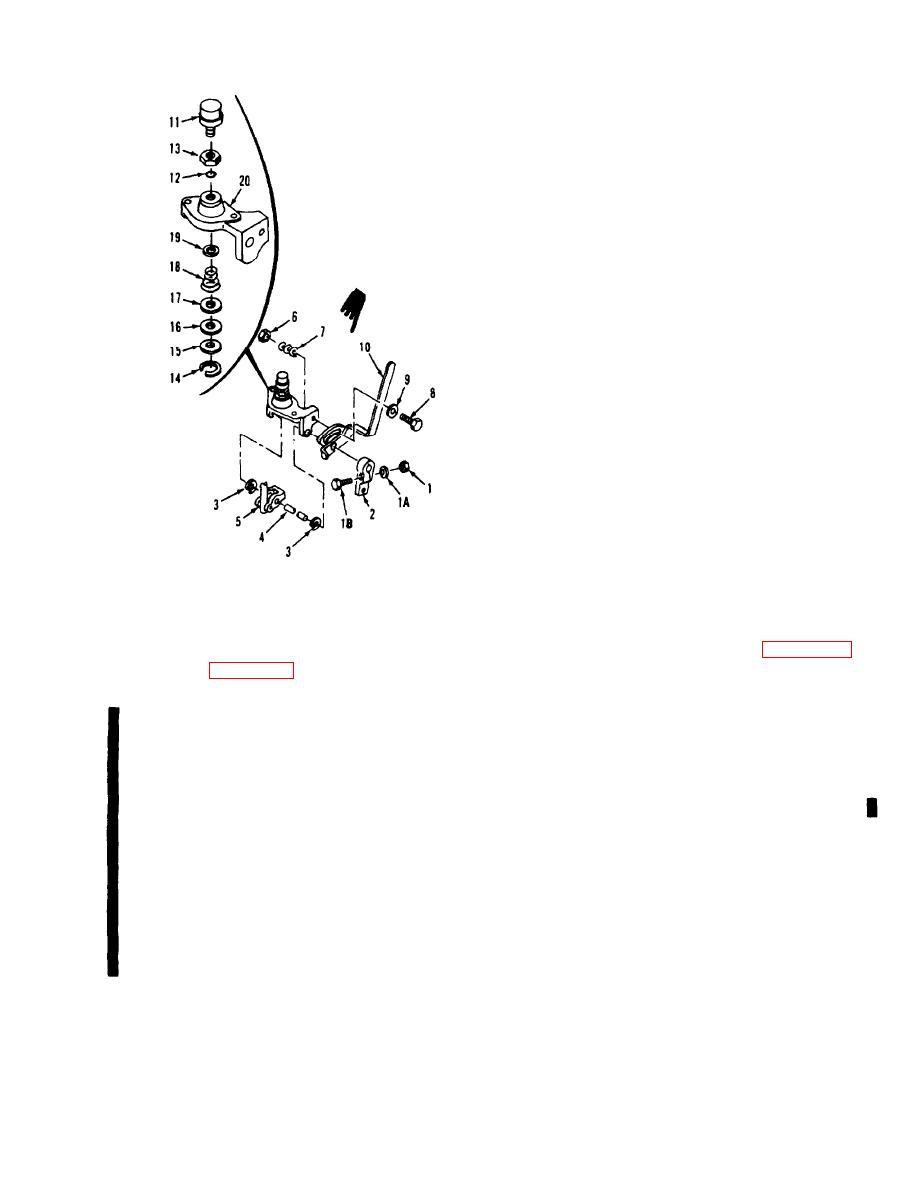
Figure 4-2. Shutter control
exploded view
4-24. REASSEMBLY. Refer to figure 4-2
and reassemble the control assembly in the
Legend to figure 4-2:
reverse order of index numbers assigned.
Pay particular attention to the following:
Power
11.
1.
Nut
1A.
Lock washer
element
a. Apply a thin film of oil to packing
1B.
Screw
12.
Preformed
(12), Position nut (13) and packing (12) on
2.
Lever
packing
power element (11). Screw power element
3.
Retainer
13,
Nut
into housing (20) until top of power element
4.
Shaft
14.
Retaining ring
is 2.75 inches above flat or flange. Hold
5.
Yoke assembly
15.
Large seat
power element stationary and tighten nut (13).
6.
Nut
16.
Felt washer
7.
Friction spring
17.
Large seat
b. Tighten nut (6) tight enough to apply
Screw
8.
18.
Spring
spring tension on manual control handle (10)
Washer
9.
19.
Small seat
and still permit movement of handle.
10.
Manual control
20.
Shutter power
handle
element
housing
4-5
Change 1


