TM 5-6115-400-35
67. Winding Resistance Measurements
a. General.
The leads of the winding to be
measured must be clean. The terminal lugs should be
cleaned with emery cloth to make sure that all foreign
matter, paint, varnish or oxide coating is removed and
only bright bare metal remains exposed for contact with
the Kelvin or Wheatstone Bridge leads. The bridge
leads shall be secured firmly to assure positive contact
with the terminal lugs.
Care must be taken to
compensate for lead resistance to the test instrument, if
such resistance is of a significant value compared to the
resistance being measured.
b. Low Resistance Measurement. To measure
resistance of less than one Ohm the Kelvin Bridge
method shall be used. In using the double bridge on
inductive circuits, the galvanometer may swing violently
when the key is depressed. This is due to the inductive
transient and may be ignored. The final steady position
of the galvnometer is the significant indication in all
cases.
c. Medium
Resistance
Measurement.
To
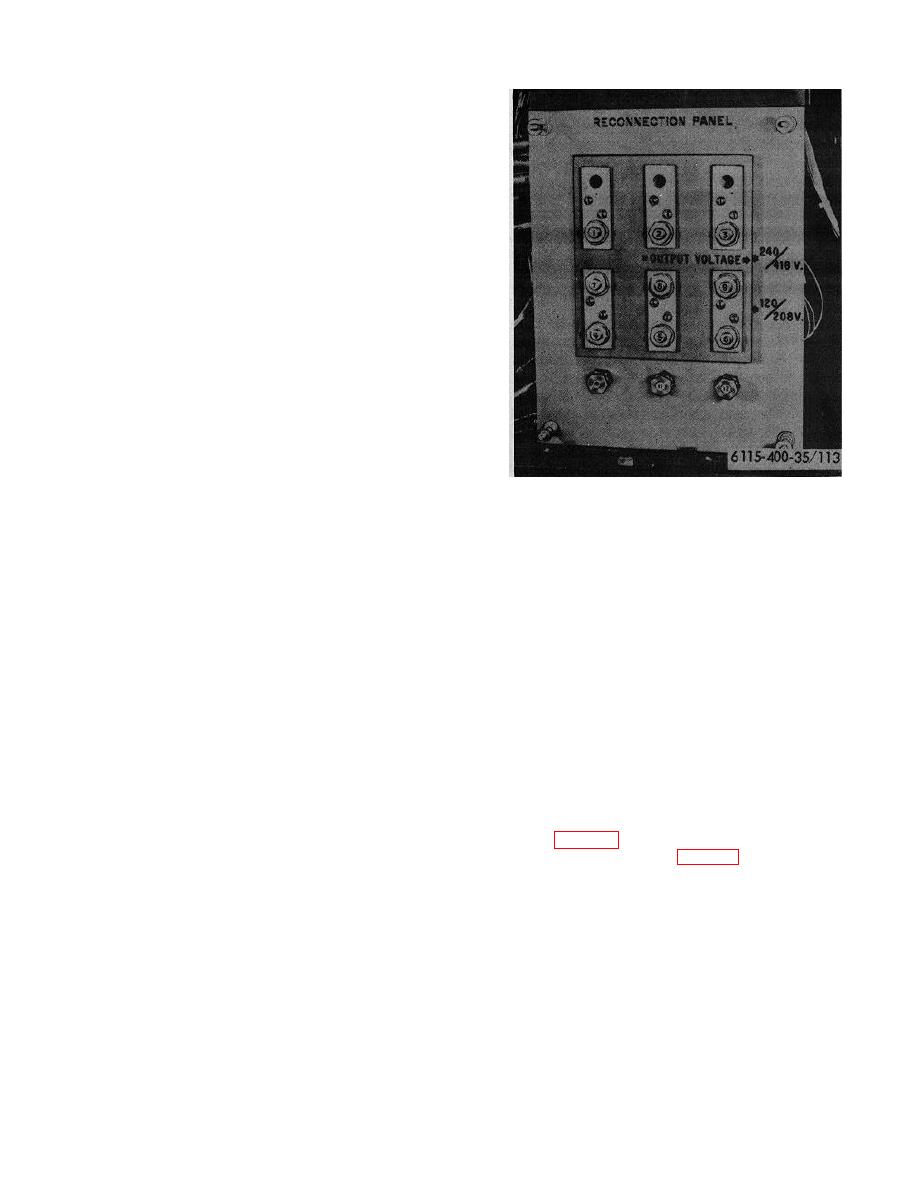
Figure 113. Reconnection panel
measure resistance of one Ohm or greater, the
Wheatstone Bridge method shall be used. In using the
Wheatstone Bridge, ratios should be selected so that the
(2) Field Winding. To measure field winding
bridge resistance corresponds as closely as possible to
resistance of more than one Ohm,
the resistance being measured.
So that the
manually lift brushes in brusholder until
galvanometer will not be subjected to an inductive
they do not make contact with the slip ring
voltage surge, use the instrument shunt key to complete
and connect a Wheatstone Bridge to the
the current circuit before the galvanometer circuit is
two slip rings.
Measure D.
C.
closed.
Resistance. Record data and disconnect
d. Test.
leads.
(1) Stator Winding.
To measure stator
68. Insulation Resistance Measurements
winding resistance of less than one Ohm,
connect the Kelvin Bridge across the
phase leads as follows:
be thoroughly dried by operating the unit at full load until
the insulation resistance becomes stabilized before
(a) Connect to T1 and T2 at the
testing.
Windings are considered dry when the
reconnection panel and read.
generator has been operated on full-load for
(b) Record data and disconnect.
approximately 2 hours under normal ambient conditions.
(c) Repeat the above on T2 and T3, T3
Disconnect the circuit under test from all other circuits.
and T1.
Disconnect Amphenol connector to the Voltage regulator
Note
The D.C. resistance of the current
connection to the rectifier (fig. 115). Securely ground
position of the CVT Transformer
all other circuits not under test. Dis-
Primary is also included in this
measurement but is negligible and
can be disregarded.
146


