TM 5-6115-400-35
(5) Turbine and Compressor Housings.
(1) Center Housing Assembly. The center
housing assembly must show no signs of
Make certain that the turbine and
contact with rotating parts. Oil passages
compressor housings are clean and have
must be clean and free of obstructions.
no internal obstructions that could impede
Inspect bearing bores for scored surfaces
the flow of gases.
and excessive wear. Using a micrometer
(6) Rotating Assembly. Every rotating part is
and a telescoping gage, measure bearing
balanced individually and can be
bore diameter. The bearing bore of the
replaced, without displacing overall
center housing must not be out of round
balance of the assembly.
or exceed .9835 inch I.D. Using a straight
(a) Compressor Impeller. Inspect the
edge and a feeler gage, check turbine
blades and bore of the compressor
shroud for distortion. Distortion must not
impeller.
Check impeller blade
exceed .005 inch.
edges and the underside of the
impeller wheel for indications of
Note.
wear. Wear occurs at these points
The shroud is not a serviceable part
as
a
result
of
excessive
If replacement is necessary, a center
bearing/thrust collar wear. Check
housing assembly, which includes
impeller surfaces for excessive and
the shroud, must be installed.
unevenly
distributed
dirt
accumulations.
Such
(2) Impeller Shaft Bearings.
Replace
accumulations disturb the precision
bearings if they show signs of scoring,
balance of the rotating assembly.
nicks, shellac deposits, or foreign material
Check to ensure that the impeller
imbedded in the metal.
wheel bore is not scratched or
scored.
Measure bearing O.D. and I.D. with a
micrometer. The dimensions of bearings
are O.D., not less than .9785 inch, I.D.
not more than .6272 inch.
(3) Thrust Bearing. The grooved side of the
thrust bearing must not be scored or have
any foreign material imbedded in its
surface. Use a micrometer and measure
overall thickness of the thrust bearing at
three points, 1200 apart.
The
measurements obtained must not be less
than .089 inch or vary more than .001
inch from one reading to the other.
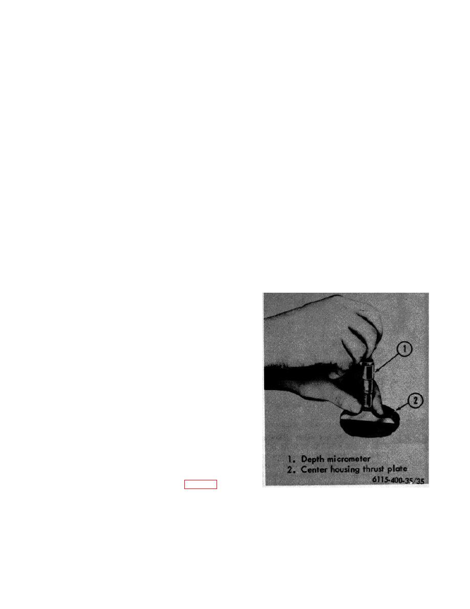
(4) Center Housing Thrust Plate. Passages
in the thrust plate assembly must be clean
and free of obstructions.
Blow out
passages with compressed air. The bore
for the sealing ring must not be scored or
rough. The thrust plate bearing surface
must not be scratched or scored. With a
depth micrometer, measure the distance
between the bearing surface and the
opposite surface of the thrust plate at
three points, 1200 apart (fig.
Figure 35. Checking center housing thrust plate
Readings obtained must not exceed .399
bearing surface for wear.
inch not vary more than .001 inch
between measurements.
70


