TM 5-6115-400-35
Caution.
If the thrust spacer moves out of
position in the thrust plate and
causes misalignment of the seal ring,
repeat this step.
(10) Check hole alignment. Install lock plates
and capscrews. Tighten capscrews to 30
to 40 in. lb. torque. Bend lock plate tabs
to secure capscrews (fig. 37F).
(11) Heat compressor impeller in a furnace,
oven, or hot oil bath at 350 for 10
F
minutes maximum.
Heated impeller
wheel will readily slip onto shaft. Install
heated impeller on shaft.
Caution.
Use asbestos gloves when handling
the hot impeller. If the compressor
impeller was not heated sufficiently
or if it cooled too rapidly, the
impeller may shrink on the shaft
before it contacts the thrust spacer.
Do not apply force.
Refer to
paragraph d, steps (7) and (8) for
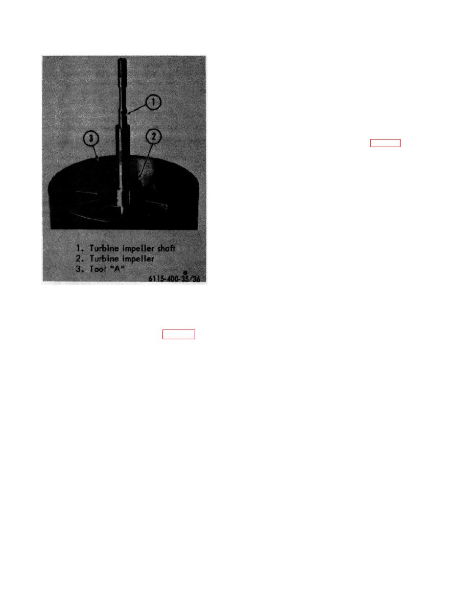
Figure 36. Turbine and shaft positioned in holding
proper' impeller removal procedure.
fixture
(5) Lubricate bearing for compressor end of
(a) Bottom or seat compressor impeller
assembly. Carefully guide impeller shaft
by installing impeller locknut.
bearing onto the shaft and into bore of the
Tighten to 150 to 160 in. lb. torque.
center housing assembly (fig. 37A).
(b) Allow impeller to cool to 150 or
F
(6) Install thrust bearing with hole and cutout
less and remove locknut. Inspect
in bearing aligned with center housing
washer contact face of nut and hub
dowel pins. Bearing must be flat against
of wheel. Both surfaces must be
the housing (fig. 37B).
smooth and clean.
Lubricate
(7) Install thrust ring on shaft, dished side up
threads and contact face of nut.
(fig. 37C).
(c) Reinstall the locknut. Position Tool
(8) Install sealing ring on thrust spacer.
H on the locknut. Mount a magnetic
base or clamp type dial indicator on
Carefully insert thrust spacer and sealing
the center housing with the indicator
ring into the center housing thrust plate.
contact point reseating on flat end
(9) Install lubricated preformed packing on
surface of shaft (fig. 37H). Set dial
center housing thrust plate. Align thrust
indicator to ZERO. Insert sliding T-
plate oil hole with matching hole in the
handle into upper end of Tool H.
center housing. Insert thrust plate into
Tighten locknut until shaft length
center housing using care to avoid
increases .006 inch to .007 inch.
disturbing position of the thrust spacer
(fig. 37E).
72


