TM 5-6115-400-35
g. Installation. Refer to TM 5-6115-400-12.
(4) Adjust operating lever high idle speed
screw until the desired full fuel quantity for
full load, as specified in paragraph 34h, is
36. Water Pump
obtained.
Adjust screw upward for
a. General.
A centrifugal-type water pump
increased delivery and downward for
assembly is provided for circulating coolant through the
reduced delivery.
engine and radiator. The pump shaft is supported in the
Note.
When a governor is
pump bearing sleeve by a ball bearing on pulley end
adjusted, there must be no rapid
and a roller bearing on rear end of the bearing sleeve.
oscillations of the fulcrum lever (41).
The bearings are splash-lubricated by oil thrown from
the engine gear train that enters through two openings in
When
this
occurs,
cause
of
the pump bearing sleeve. Lip-type oil seals at each end
fluctuations must be found and
of the bearing sleeve prevent oil from leaking to the
corrected before proceeding further.
outside and from entering the impeller compartment of
(5) If step 4 has been correctly established,
the pump body. A spring-loaded coolant seal prevents
then a slight increase in test stand rpm
coolant from seeping out of the impeller compartment.
will start control rack moving toward the
The tapered hub of the impeller is "pinned" to the rear of
stop position, thus reducing the fuel
the pump shaft and is secured by a slotted nut and
delivery.
cotter pin.
(6) Again operate test stand at governed full
b. Removal. Refer to TM 5-6115-400-12.
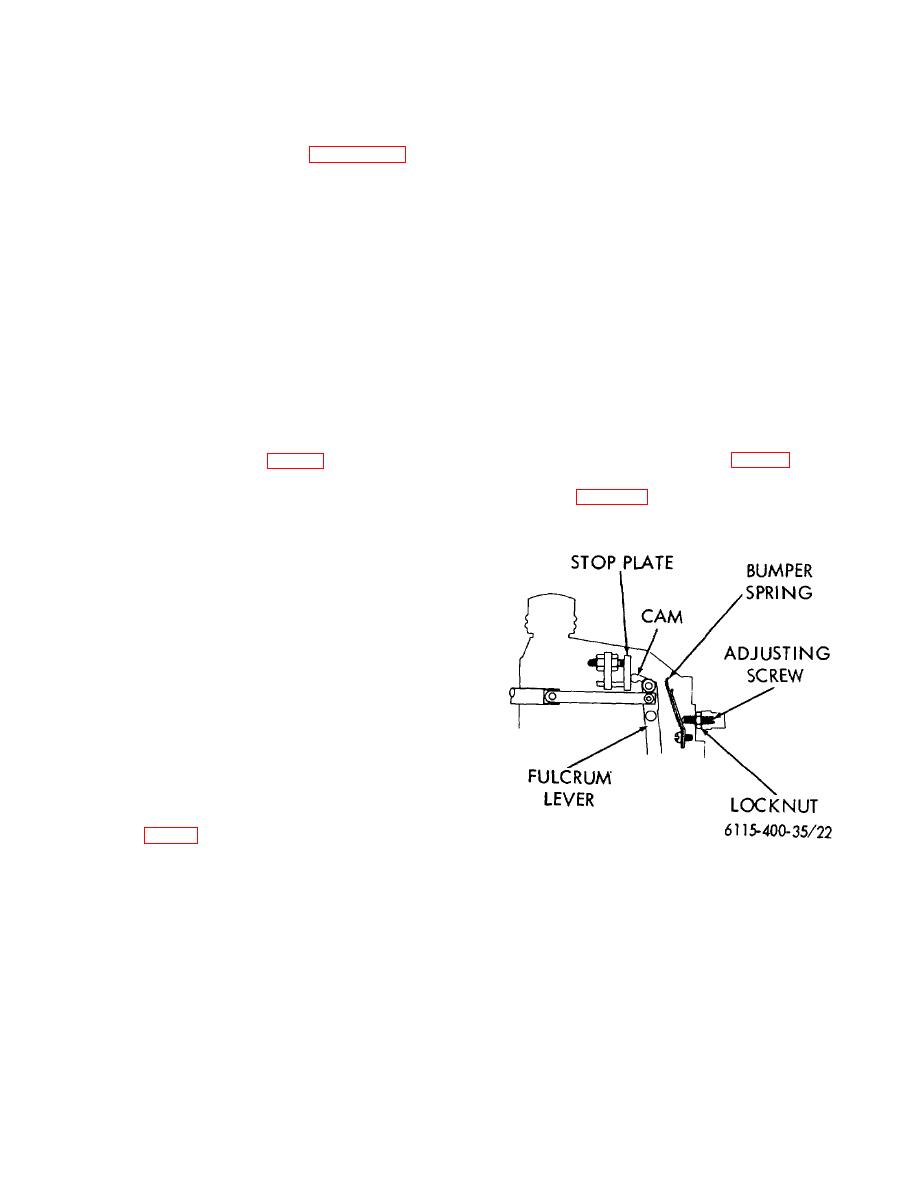
load rpm and adjust stop plate (68) to just
contact cam (See fig. 22). Then inscribe
line on the machined surface of governor
(1) Clamp pulley hub in a vise as shown in
housing with straight edge across front
face of stop plate.
with copper protectors.
(7) Record fuel delivery taken at this setting
and rpm.
(8) Check for torque control by reducing rpm
to 2/3 of full load speed.
Holding
operating lever in full load position, an
increased fuel delivery will result.
(9) With operating lever still in full load
position, increase rpm to high idle rpm.
The control rack should have moved into
decreased fuel delivery position and
reduced fuel approximately 1/4-1/5 of full
load quantity. Record delivery for same
number of strokes as taken at rated full
load rpm.
(10) With pump operating at high idle rpm as
set in step 9 (and operating lever in full
load position) turn in adjusting screw (See
the fulcrum lever. In the event that slight
oscillation is present in the fulcrum lever
Figure 22. Governor bumper spring adjustment.
at this higher rpm, screw in bumper spring
screw in this position with lock nut and
cap.
(11) The high and low idle setting can only be
approximated on the test stand, as the
actual idle settings must be made on the
engine.
54


