
TM 5-6115-400-12
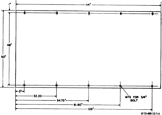
Length.......................................114 In.
(18) Capacities.
Width ........................................ 50 in.
Fuel Tank..................................200 gal
Height ....................................... 75 in.
Governor hydraulic....................2 gal.
Weight (dry-approx.) ................. 10,000 lbs.
Engine lubricating ..................... 11 gal.
Figure 1-3. Wiring diagram
Cooling system ......................... 70 qt
Located in back of manual
(19) Nut and Bolt Torque Data.
Fuel injection pump...................40-45 ft. lbs.
1-5. Difference in Models
coupling capscrew.
Oil filter center bolt....................45-50 ft. lbs.
This manual covers only the Military Standard
Nozzle holder clamp nut............21-24 ft. lbs
Model SF-200-MD/CIED (Allis-Chalmers Model 25000-
Fuel injection line nut ................ 20-25 ft. lbs.
4444650) generator set. No known unit differences exist
Oil pressure regulating .............. 125-135 ft. lbs.
for the model covered by this manual.
Screw lock nut
(20) Dimensions and Weight.
Figure 1-4. Base plan
1-6