b.
c.
d.
e.
f.
g.
TM 9-6115-659-13&P
The second generator set is now supplying electric power to the connected load. All
SYNCHRONIZING lights (1 and 9) should be dark.
Refer to TM 9-6115-641-10 and set AC CIRCUIT INTERRUPTER switch for generator set that
is now offline to OPEN position.
Check that switch box ON/OFF switch (6 or 4) for the offline generator set is at center position.
Refer to TM 9-6115-641-10 and:
(1) Shut down generator set that is now off line.
(2) Using generator set VOLTAGE adjustable rheostat, adjust voltage of generator set that is
now on line to the desired value.
(3) Using generator set frequency adjust control, adjust frequency of generator set that is now
on line to desired value.
Refer to table 2-2 and perform “After” PMCS for the generator set that was shut down.
For the generator set that is now ON LINE, perform the PMCS listed as “During” in table 2-2.
2-5.3.3 Stopping Generator Set.
a. Set the switch box ON/OFF switch (6 or 4, figure 2-10) for the generator set to be stopped to
OFF position.
b. Stop the generator set in accordance with TM 9-6115-641-10.
c. Perform the generator set PMCS listed as “After” in table 2-2.
2-6 IDENTIFICATION AND INFORMATION PLATES.
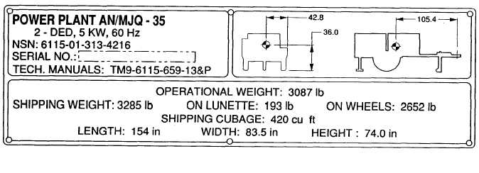
2-6.1 AN/MJQ-35 Identification/Transportation Data Plate. Refer to figure 2-11. This plate is
located on rear of curbside fender.
Figure 2-11. AN/MJQ-35 Identitication/Transportation Data Plate.
2-39


