TM 9-6115-659-13&P
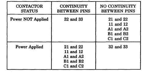
Table 5-5. Contactor Operation
3. If all multimeter indications are correct, install contactor terminal shield (3), four flat washers (2), and
screws (1).
4. Replace contactor if any multimeter indication is not as listed in table 5-5.
INSTALLATION
1.
2.
3.
4.
5.
6.
7.
8.
9.
Position contactor K1 or K2 (9) on studs (20).
Install four flat washers (19), lock washers (18), and nuts (17).
Refer to wiring diagram (figure FO-1) and tags installed in removal. Connect applicable terminal lugs
of W9 wires to contactor terminals (16) X, Y, 11, 12, 21, 22, 32, and 33. Remove tags.
If terminal shields (3) of contactor are installed, remove four screws (1), lock washers (2) and terminal
shields (3).
Remove nuts (4), lock washers (5), and flat washers (6) from contactor terminals (8) A1, B1, C1, A2,
B2, and C2.
NOTE
Leads W3, W4, and W5 (13, 14, and 15) must be installed along with leads W6, W7,
and W8 when contactor K1 is being installed.
Place free ends of jumpers W6, W7, and W8 (10, 11, and 12) on contactor K1 (15) terminals (16) Al,
B1, and C1.
Install flat washer (6), lock washer (5), and nut (4) on terminals (8) for A1, B1, and C1. Tighten
nuts (4).
Place power cable leads (7) on contactor terminals (8) A2, B2, and C2. Remove tags.
Install flat washers (6), lock washers (5), and nuts (4) on contactor terminals (8) A2, B2, and C2.
10. Install terminal shields (3), two lock washers (2) end screws (1) on contactor (9).
5-35