TM 9-6115-659-13&P
NOTE
Maintenance of switch box assembly consists of testing, removal, and
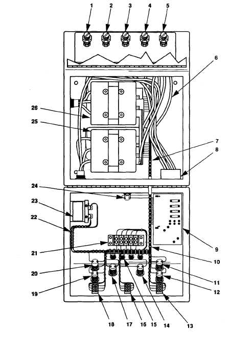
installation of switch box wiring and other switch box components. Figure
5-8, Switch Box Components, is provided as an aid in performing the following
maintenance procedures.
LEGEND
1.
2.
3.
4.
5.
6.
7.
8.
9.
10.
11.
12.
13.
14.
15.
16.
17.
18.
19.
20.
21.
22.
23.
24.
25.
26.
GND TERMINAL
TERMINAL L0
TERMINAL L3
TERMINAL L2
TERMINAL L1
PART OF OUTPUT CONN
HARNESS W10
SW BOX HARNESS W9
OUTPUT CONN
RELAY BOARD ASSY
SEE 7
IND LIGHT HSG XDS2
IND LIGHT HSG XDS4
SWITCH S2
IND LIGHT HSG XDS6
HOUSING FOR SPARE LAMP
(ONE OF FOUR)
SWITCH S10
IND LIGHT HSG XDS5
SWITCH S1
IND LIGHT HSG XDS3
IND LIGHT HSG XDS1
TERMINAL BOARD TB2
SEE 7
RELAY PP
IND LIGHT HSG XDS7
CONTACTOR K1
CONTACTOR K2
Figure 5-8. Switch Box Components.
5-15

