TM 9-6115-604-34
NAVFAC P-8-633-34
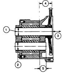
REF.
MEASUREMENT
NEW MINIMUM
NEW
MAXIMUM
WEAR LIMIT
NUMBER
1
BUSHING
1.5025
1.5040
1.505
INSIDE
(38.164)
(38.202)
(38.23)
DIAMETER
2
IDLER AND
1.4995
1.5000
1.4993
DRIVE SHAFT
(38.087)
(38.100)
(38.082)
OUTSIDE
DIAMETER
3
DRIVE SHAFT
0.004
0.007
END
(0.10)
(0.18)
CLEARANCE
4
PROTRUSION
2.460
2.480
FROM GEAR
(62.48)
(62.99)
5
IDLER SHAFT
1.280
1.300
PROTRUSION
(32.51)
(33.02)
FROM GEAR
Figure 8-7. Lubricating Oil Pump Fits and Clearances
8-13.
OIL PUMP ASSEMBLY. See Figure 8-4.
a.
Install the lubricating pump shaft and gear (45 and 44) into the lubricating pump body (47).
b.
Support the lubricating pump shaft (45) and press the lubricating pump drive gear (43) on the shaft until it is
flush with the end of the shaft.
c.
Install the lubricating pump shaft and gear (42 and 41) into the lubricating pump body (47).
d.
Position a new lubricating pump gasket (40) on the pump body, and install the cover (39), hexagon head
capscrews (37), and lockplates (38) and tighten to 30 to 35 pound-feet (41 to 47 newton-meters) torque.
Bend the tabs on the lockplates to secure the capscrews.
e.
Check the shaft end clearance (3, Figure 8-7). The end clearance shall be 0. 004 to 0. 007 inch (0. 10 to 0.
18 mm). If the end clearance is incorrect, replace the cover (39, Figure 8-4).
f.
Position the relief plunger (36), relief spring (35), and plain washer (34) into the pressure relief housing (30).
Secure with the retaining pin (33) and roll pin dowel (32).
CAUTION
It is possible to install the of oil transfer tube (23) in a reverse
position (wrong end to the lubricating pump). Whenever this
happens, the support bracket (6) for the oil suction tube (9) will not
fit. Install the long end of the transfer tube to the pressure relief
housing (30) connection on the lubricating oil pump.
g.
Lubricate the supply tube seal (20) with clean engine lubricating of MIL-L-2104, or equivalent, and position it
on the long-bend end of the transfer tube (23). Use a new relief gasket (31) and install the pressure relief
housing assembly (30) and transfer tube (23) with supply tube seal (20) to the lubricating pump cover (39)
with capscrews (21) and lockplates (22). Finger-tighten the capscrews (21) only.
h.
Install lubricating pump cover (29) and secure with capscrews (1 7) and lockplates (18).
8-11