TM 9-6115-604-34
NAVFAC P-8-633-34
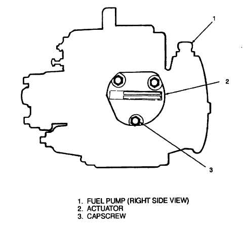
Figure 6-6. Actuator Capscrew, Torque Sequence
(f) Rotate the actuator (4) in a counterclockwise direction to align the mounting holes, and install the
capscrews (1), lockwashers (2), and washers (3) as follows:
1
See Figure 6-6 and tighten the capscrews (3) 1/8 turn in the sequence shown.
2
Tighten the capscrews (3) in the sequence shown, in three steps, to 25 pound-inches (2.8
newton-meters), to 50 pound-inches (5.6 newton-meters), and to a final torque of 75 pound-
inches (8.5 newton-meters).
3
Loosen all three capscrews (3) completely, and retighten as in steps 1 and 2. above.
(g) Recheck the operation of the actuator (4) as in step (b), above. Loosen all three capscrews (1) and
retighten as in step (f), above, if the same distinct click is not heard during this test.
f.
Install.
(1)
Place the spider (19, Figure 6-12) on the fuel pump drive coupling (23) and secure for assembly with
masking tape, such as A-A-883A.
(2)
Install the fuel pump assembly (36, Figure 6-5) with a new gasket (32) onto the accessory drive (6, Figure
6-4) with capscrews (33, Figure 6-5), lockwashers (34), and washers (35). Cross-tighten the capscrews to
40 to 45 pound-feet (54 to 61 newton-meters).
(3)
Install the speed switch SS1/SS2/SS3 (4, Figure 6-4) into the mainshaft, cover, governor assembly (31,
Figure 6-5).
(4)
Install electrical connector J1 (3, Figure 6-4) to the speed switch SS1/SS2/SS3.
6-11