TM 9-611560434
NAVFAC P+633-34
Figure 5-14. Load Circuit Breaker CB101, Rear View (Sheet 1 of 2)
(1)
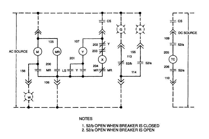
Drive Spring Charging. Assume that the interrupter contacts are in the open position and that the drive springs
(Figure 5-15) and the return springs (Figure 5-16) are discharged. When power is supplied to the breaker control
circuitry, the spring charging motor (Figure 5-15) is energized. The motor eccentric (Figure 5-17), mounted on the
charging motor shaft, drives the ratchet arm assembly backward and forward. With each forward stroke of the ratchet
arm, the spring loaded drive on the gear advances the gear a few degrees counterclockwise. The holding pawl holds the
gear in position while the drive pawl makes its reverse stroke to engage another tooth. The gear is free to rotate on the
gear shaft. As the gear is advanced, the drive block, mounted on the outside face of the gear, engages the gear on the
drive hub and rotates the drive hub. A roll pin connects the drive hub to the gear shaft and drive lever (Figure 5-15).
The gear shaft and drive lever thus rotate with the drive hub. As the drive lever rotates, the lifting roller on the drive
roller contacts the lift arm on the drive shaft (Figure 5-17) and pushes the lift arm up, rotating the drive shaft
counterclockwise. The counterclockwise drive shaft rotation compresses the drive springs until the spring load against
the drive lever passes top dead center and attempts to discharge. At this point, the drive lever rotates a few degrees
until the trip closing roller (Figure 5-15) on the drive lever can rotate no farther and the drive springs are held on this
charged position until a closing operation is initiated. When the drive springs reach the fully charged position, the
charging motor limit switch cam (Figure 5-16) allows the charging motor limit switch to open, deenergizing the charging
motor. Simultaneously, the pawl lift slide (Figure 5-17) is pushed forward by the cam lobe on the drive hub so that the
drive pawl rides on the pawl lift slide and does not engage the gear. This arrangement allows the charging motor and
ratchet assembly to coast smoothly to a stop.
5-36


