TM 9-6115-60434
NAVFAC P+633-34
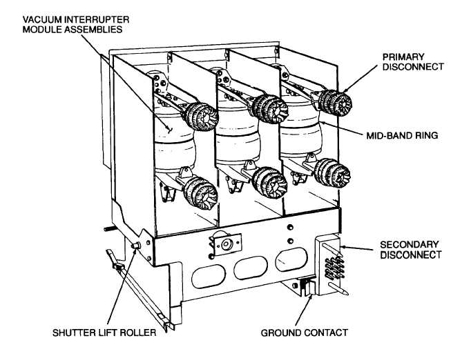
Figure 5-13. Load Circuit Breaker CB101, Rear View
f.
Manual Charge Arm Assembly. The drive springs (Figure 5-15) can be manually charged by using the handle end
of the racking crank (located on the lower inside door of Cabinet B) to move the manual charge arm (Figure 5-12) up and
down until the drive springs are fully charged. The drive springs are fully charged when the CHARGE-DISCHARGE
indicator reads charged and the manual charge arm can no longer be raised.
g.
Secondary Disconnect Slide Handle. The secondary disconnect slide handle (Figure 5-12) Is used to engage and
disengage the secondary disconnect slide (193, Figure 5-19) when performing secondary control power testing of load
circuit breaker CBI 01. This is accomplished only after load circuit breaker CB1 01 has been partially withdrawn from its
cubicle in lower cabinet B, the primary disconnects are disengaged, and the circuit breaker is In a safe condition with no
high voltage current present. To operate the secondary disconnect slide handle, lift the handle to a horizontal position.
Continue lifting the handle until it clears the catch and then push the handle into the circuit breaker just until the roll pin in
the catch engages and locks the handle in position.
h.
Operating Mechanism. The following is a description of the operation of the operating mechanism. This manual
will refer to the operating mechanism as the front of the breaker. The terms left and right will be used as if facing the
operating mechanism. The terms clockwise and counterclockwise will be used as if facing the left side of the breaker.
5-35