TM 9-6115604-34
NAVFAC P8633-34
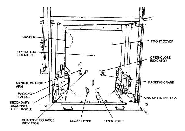
Figure 5-12. Load Circuit Breaker CB101, Front View, Installed
b.
Charging Motor Limit Switch. Charging motor limit switch LS (Figure 5-16) energizes the motor relay MR (Figure
5-15) when a drive spring charging operation is required and deenergizes the motor relay when the drive springs (Figure
5-15) reach the fully charged position. As shown in the schematic diagram (Figure 5-14), charging motor limit switch LS
is connected in the normally open position. Whenever the drive springs are not in the fully charged position, the charging
motor limit switch cam (Figure 5-16) actuates the charging motor limit switch. The cam allows the switch to assume its
normally open position once the drive springs are fully charged.
c.
Motor Relay. When energized by the closing of motor limit switch LS (Figure 5-14), motor relay MR energizes the
spring charging operation limit motor M through a pair of normally open contacts and disables the closing solenoid X
through a pair of normally closed contacts.
d.
Anti-Pump Relay. Anti-pump relay Y (Figure 5-14) ensures that, should the control switch CS (which energizes the
closing solenoid) be continuously maintained in the closed position, the springs will not be continuously charged and
discharged. Anti-pump relay Y performs this function by allowing the closing solenoid to be energized only if the control
switch CS (Figure 5-14) is closed after the drive springs have reached the fully charged position, and motor relay MR has
been deenergized. The anti-pump relay Y will be energized if control switch CS is closed and motor relay MR is
energized. If the control switch is held continuously, the anti-pump relay will be latched in the energized position after the
motor relay is deenergized by a pair of its own normally open contacts. When the anti-pump relay Y is energized, a pair
of its normally closed contacts, in series with the closing solenoid, ensures that the closing solenoid cannot be energized
by the control switch. The closing solenoid cannot be energized unless the control switch is first opened (deenergizing
the anti-pump relay), then closed again.
e.
Indicators. Two indicators are provided on the operating mechanism. The OPEN-CLOSE indicator (Figure 5-12)
designates the position of the vacuum interrupter contacts. The CHARGE-DISCHARGE indicator displays the state
(charged or discharged) of the drive springs.
5-34


