TM 9-6115-604-34
NAVFAC P-8-633-34
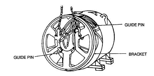
Figure 5-6. Bracket Installation
(1)
Install bracket (19) on stator coil assembly (33) in accordance with step a, above.
WARNING
Do not use a lifting device with a capacity of less than 4,000 pounds (1 600kg)
when lifting rotor assembly (15). Failure to observe this warning may result In
serious Injury or death to personnel.
(2)
Using a rotor lifting fixture and a suitable hoist (see Figure 5-5), carefully install the rotor assembly (15,
Figure 5-1) into the stator coil assembly (33) through the drive end. Carefully feed the taped rotor leads
through the bracket shaft hole as the rotor is installed (see Figure 5-7).
WARNING
Do not use a lifting device with capacity of less than 215 pounds (98 kg) when
lifting machining adapter (25). Failure to observe this warning may result in
serious injury or death to personnel.
(3)
Attach a suitable hoist with a capacity of 215 pounds (98 kg) to the machining adapter (25). See Figure 5-
4.
(4)
Pilot the machining adapter (25, Figure 5-1) to the fan (55) and secure to the coil assembly (33) with
hexagon head screws (26) and lockwashers (27). Torque hexagon head screw (26) to 60 pound-feet (68
newton-meters). It may be necessary to raise the rotor assembly (15) slightly to allow the mounting of the
machining adapter (25).
(5)
Insert a guide stud into the hub (23).
(6)
Install two spacers (24) and ten coupling drive discs (22), one at a time. Make sure all coupling drive disc
mounting holes at the inner and outer diameter are properly aligned.
(7)
Remove the guide stud and secure the coupling drive discs (22) with hexagon head screws (20) and plain
washers (21). Torque in accordance with to 216 pound-feet (293 newton-meters).
(8)
Check the torque of each bolt in a clockwise direction around the bolt circle to ensure that all bolts are
properly torqued.
(9)
Mount the screen assembly (3) and drip cover assembly (4) to the machining adapter (25) and secure with
hexagon head screws (1) and hexagonal nuts (2).
(10)
Insert two sets of hexagon head screws (16) and lockwashers (17) into the bracket (19) and secure the
bearing cap (1 8).
5-20


