TM 9-6115-604-34
NAVFAC P-8-633-34
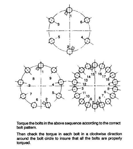
Figure 5-8. Torque Sequence, Drive Discs
e.
Exciter Rotor Assembly.
(1)
Using a safety wire of adequate length, feed through the lead hole in the aluminum standoff (14, Figure 5-1
inside the exciter rotor assembly (13). Remove tape from main rotor field wires (if field wires were taped to
the shaft).
(2)
Install the mounting key (58) in the main rotor assembly (15) shaft keyway.
(3)
Position exciter rotor assembly (13) for installation. Attach one end of the safety wire coming through the
lead hole in the aluminum standoff (14) to the two main rotor field wires coming out of the main rotor
assembly (15) shaft.
(4)
Align keyway at rear of aluminum standoff (14) with the key (58) installed on main rotor assembly (15)
shaft. Slide the exciter rotor assembly (13) on the main rotor shaft while carefully pulling the main rotor
field leads through the lead hole in the aluminum standoff (14) with the safety wire.
(5)
Position the belleville washer (9) on the hexagon head screw (12) with its indented side facing away from
the screw head. (See detail inset, Figure 5-1. Belleville washers should always be positioned as shown.)
Insert the hexagon head screw (12) and belleville washer (9) through the mounting hole in the aluminum
standoff (14) and secure to the main rotor shaft. Tighten until the exciter rotor assembly (13) seats fully on
the shaft. Torque hexagon head screw (12) to 95 pound-feet (129 newton-meters).
5-22