TM 9-6115-604-34
NAVFAC P-8-633-34
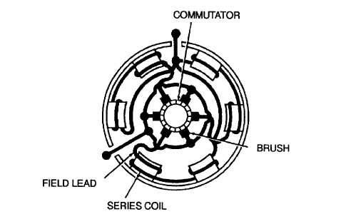
Figure 4-4. Starter Motors B1 and B2, Location of Field Loads
(6)
Visually inspect the frame and housing for cracks or other damage that would impair proper operation.
(7)
Check the threaded parts for crossed, deformed, or stripped threads.
(8)
The drive housing and housing lever bushings (24 and 32) and the sleeve bearing (45) are a press fit in
their respective bores, with clearance of -0.0005 to -0.0020 inch (-0.013 to -0.051 mm). Check that they
are a tight fit, and show no signs of rotation in the bores.
(9)
Check the drive housing and housing lever bushings (24 and 32) and sleeve bearing (45) for scoring and
proper fit on armature (63). Clearance shall not exceed 0.006 inch (0.15 mm).
(10)
Visually inspect the armature (63) for the following defects: scored or grooved bushing surfaces, damaged
laminations due to rubbing on the pole rotor shoes (58), burned or scored commutator bars, high insulation
between commutator bars, loose commutator bars, damaged splines, and damaged or loose windings due
to thrown solder.
(11)
Check the armature (63) for shorted or open windings using an armature growler. Refer to Figure 45.
WARNING
Failure to exercise caution when using energized test equipment may result In Injury to
personnel.
(12)
Using a 110V ac test lamp or multimeter set to RX1 scale, check each commutator bar for grounds and
continuity. Refer to Figure 4-6.
(13)
Using V-blocks and a dial indicator, check the total indicated runout (TIR) of the armature (63, Figure 4-3)
at the laminations, and at the commutator. TIR shall not exceed 0.005 inch (0.13 mm).
(14)
Visually check the field coils (61, Figure 43) and leads for damaged insulation or oil soaking.
WARNING
Failure to exercise caution when using energized test equipment may result In Injury to
personnel.
4-10


