ARMY TM 9-6115-464-12
AIR FORCE TO 35C2-3-445-1
NAVY NAVFAC P-8-624-12
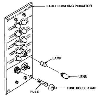
Figure 4-40. Fault Locating Indicator Lamp and Fuse Replacement
(3) Replace lamp if defective.
(4) Install lamps and lens.
d. Fuse Replacement.
(1) Unscrew cap (Figure 4-40) and remove fuse.
(2) Visually inspect fuse for corrosion, cracked or broken glass, and melted conductor.
(3) Replace fuse if defective.
(4) Install fuse and cap.
e.
Removal.
(1) Disconnect wiring harness from back of fault locating indicator.
(2) Remove screws (1, Figure 4-41) and Iockwashers (2) to remove fault locating indicator from generator
set.
f.
Disassembly.
(1)
(2)
(3)
(4)
(5)
(6)
Remove screw and captive washer assemblies (3) and cover plate (4).
Remove screw and captive washer assemblies (5) and carefully pull indicator panel assembly (6)
away from housing. Tag and disconnect electrical leads.
Disassemble panel assembly (items 7 through 24) only as is necessary for replacement of damaged
or defective components.
Remove screw and captive washer assemblies (25) to remove cover plate assembly (26). Tag and
disconnect electrical leads.
Disassemble cover plate assembly (items 27 through 32) only as is necessary for testing and replacement
of components.
Remove screw and captive washer assemblies (33) to remove wiring harness (34) from housing (35).
g.
Installation.
(1) Install fault locating indicator to generator set with lockwashers (2 , Figure 4-41) and screws (1).
(2) Connect wiring harness to back of fault locating indicator.
4-101