TM5-6115-634-14&P
NAVFAC P-8-647-14&P
T0-35C2-3-445-14
TM-6115-14&P/1
MAINTENANCE OF CONTROL WIRING HARNESS
5-17.
REPAIR OF CONTROL WIRING HARNESS
This task covers: a. Removal
c. Repair
b. Test
d. Installation
INITIAL SETUP
Tools
Equipment Conditions:
Reference
General Mechanic’s Tool Kit
Para. 4-9 General Instructions.
5180-00-177-7033
Multimeter
6625-01-139-2512
Materials/Parts
Control Wiring Harness
97403-13228E1909
Connector, Receptacle
97403-13228E1949
Connector J45
81349-D38999/24-F-D-5S
Connector P15
96906-MS31O6R2O-29P
General Safety Instructions
To avoid short circuits which could
damage equipment or injure personnel,
always disconnect negative battery
cable before performing maintenance
on the electrical system.
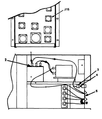
REMOVAL
REMOVE CONTROL
a.
Disconnect
WIRING HARNESS.
connector P-15 (1)
b.
c.
d.
5-20
from special relay assembly
J15 (2).
Disconnect the SS2R connector
(3) from the SS2P connector
(4).
Remove the nut from connector
J45 and remove the cable
connector from the connector
plate (5).
Remove the control wiring har-
ness by feeding it down through
the relay table and out of the
generator set.